Now that I have completed the installation of the axle and landing brake, I
turned the fuselage over for the long awaited lip. The landing gear lips are
made out of two 6-ply BID strips, conformed to a 90o angle along the
entire length of the landing brake cover.
 I
roughed up about a 1.5" wide surface strip along the LG bulkheads (forward &
aft) with 36 grit sandpaper in preparation for the BID tapes. I put packing tape
along the 1" edge at the underside of the landing cover. I should have put a
wider strip and I sweated over that later. Note that if the cover ever gets
epoxied to the lip, you would have a heck of the time separating the two...
I
roughed up about a 1.5" wide surface strip along the LG bulkheads (forward &
aft) with 36 grit sandpaper in preparation for the BID tapes. I put packing tape
along the 1" edge at the underside of the landing cover. I should have put a
wider strip and I sweated over that later. Note that if the cover ever gets
epoxied to the lip, you would have a heck of the time separating the two...
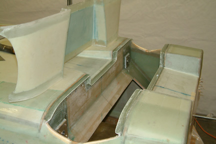
I placed the cover over the strut opening, making sure its nice and straight,
weighed it down and hot glued the cover in place. I put enough hot glue to make
sure nothing moves or any chance of falling off when the fuselage is turned
over.
I made 6, 2x38", 2-ply BID tapes for the cover lips because I was concerned that
a single 6 ply BID may not want to conform well around the bends of the landing
cover. Its more work, but the results should be better.
It was a challenge to lay the 2 ply BID tapes nicely and I ended up with ~3/4"
over the under side of the cover edges (now covered with packing tape) and then
the 90o bend along the face of the LG bulkheads. It took me a good 6
hours to perform this entire task. After cure, I trimmed them out and they are
stiff and strong. It also provides a very nice snug fit for my cover.
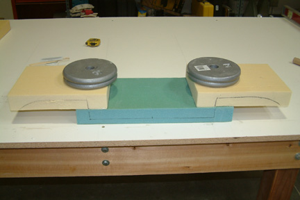 I
gathered 3 blocks of 2" thick urethane foam and trimmed them to size. The
bottom one (green) is 8"x14" while the other two (yellow) are 8"x11". I trial fit them in place and traced the joining surfaces on the
sides of the foam, such that I can fit them back onto the same place (note the
lines on the sides of the foam). I made them a bit tight so that I can force
them into the space between the LG bulkheads. Then I microed them together as
shown.
I
gathered 3 blocks of 2" thick urethane foam and trimmed them to size. The
bottom one (green) is 8"x14" while the other two (yellow) are 8"x11". I trial fit them in place and traced the joining surfaces on the
sides of the foam, such that I can fit them back onto the same place (note the
lines on the sides of the foam). I made them a bit tight so that I can force
them into the space between the LG bulkheads. Then I microed them together as
shown.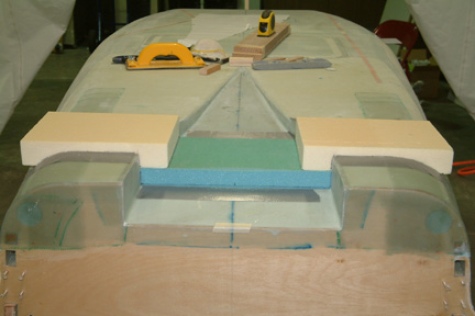 Once
the micro was cured, I force fit the foam block back into the bulkhead slot for
sanding. Note the sanding blocks I used for sanding.
Once
the micro was cured, I force fit the foam block back into the bulkhead slot for
sanding. Note the sanding blocks I used for sanding. Once
I got the outer contour close to the surface of the fuselage, I dug out the original
NACA scoop paper template and traced out the inner contours. Note I used my laser
for alignment and my
Once
I got the outer contour close to the surface of the fuselage, I dug out the original
NACA scoop paper template and traced out the inner contours. Note I used my laser
for alignment and my 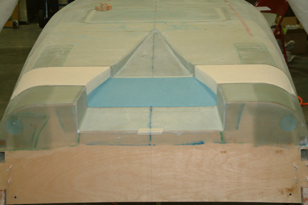 With
the shaping
of the contour completed, I applied 2" packing tape along the seam
of the cover and the fuselage. Roughly 1" over the cover and 1" over
the fuselage. Ready for glassing!
With
the shaping
of the contour completed, I applied 2" packing tape along the seam
of the cover and the fuselage. Roughly 1" over the cover and 1" over
the fuselage. Ready for glassing!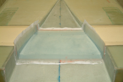 Referencing
the method I used for the first part of the NACA scoop in Chapter 7 page 2, I
first glassed the inside of the cover with 2 layers of BID and allowed to cure
overnight.
Referencing
the method I used for the first part of the NACA scoop in Chapter 7 page 2, I
first glassed the inside of the cover with 2 layers of BID and allowed to cure
overnight.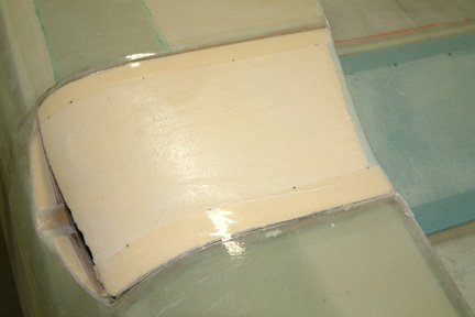 Once
cured, I trimmed off the excess glass along the top edge of the NACA scoop.
Then I used my Dremel and dug a V groove along the sides of the newly glassed
cover. I packed in some relative dry flox into the groove. This step is
necessary to ensure a sharp corner along the bottom edge of the NACA scoop (per
plan). Note the packing tape for mold release as mentioned above.
Once
cured, I trimmed off the excess glass along the top edge of the NACA scoop.
Then I used my Dremel and dug a V groove along the sides of the newly glassed
cover. I packed in some relative dry flox into the groove. This step is
necessary to ensure a sharp corner along the bottom edge of the NACA scoop (per
plan). Note the packing tape for mold release as mentioned above. 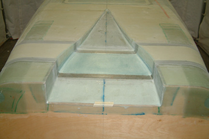 Before
the flox is cured, I applied 2 layers of BID onto the rest of the cover and
allowed to cure. Right before I lay down the BID, I brushed pure epoxy on top of
the flox to get a smooth flox surface. Again, I trimmed off the excess glass
after cure.
Before
the flox is cured, I applied 2 layers of BID onto the rest of the cover and
allowed to cure. Right before I lay down the BID, I brushed pure epoxy on top of
the flox to get a smooth flox surface. Again, I trimmed off the excess glass
after cure. The
next step is to trim the ends of the cover to accommodate the main landing gear.
I mounted the landing gear back in place and used the carpenter's widget and
traced out the profile of the landing gear surface. Then I transferred the
profile onto the left and right ends of the cover and trimmed with my FEIN tool
and sand paper. Note the uniformity of the cover edge to the strut surface.
Eventually, an external cover will be made to cover them all up and nobody will
see this - you'll be the only person that appreciates this work...
The
next step is to trim the ends of the cover to accommodate the main landing gear.
I mounted the landing gear back in place and used the carpenter's widget and
traced out the profile of the landing gear surface. Then I transferred the
profile onto the left and right ends of the cover and trimmed with my FEIN tool
and sand paper. Note the uniformity of the cover edge to the strut surface.
Eventually, an external cover will be made to cover them all up and nobody will
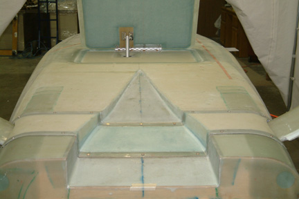
see this - you'll be the only person that appreciates this work...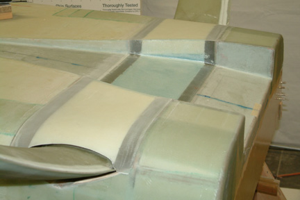 Here's
a picture with the gear mounted and the cover in place. It is gratifying to see
various parts you build are fitting together!
Here's
a picture with the gear mounted and the cover in place. It is gratifying to see
various parts you build are fitting together! 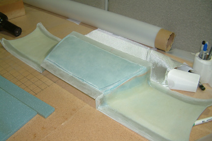 After
I glassed the underside of the landing gear cover, I sat it on its back for cure
- that was a big mistake. The vertical walls spread a little and the middle of
the cover sagged a little. By the time the cover was cured, I got a stiff cover
that won't fit in the landing gear slot. After I force fit it, I got a
3/16" gap right at the middle of the NACA scoop. The cover was stiff enough
that there is a good chance that I will not be able to pull it down flat even
with the holding screws. I was debating whether to re-make
the part or repair it.
After
I glassed the underside of the landing gear cover, I sat it on its back for cure
- that was a big mistake. The vertical walls spread a little and the middle of
the cover sagged a little. By the time the cover was cured, I got a stiff cover
that won't fit in the landing gear slot. After I force fit it, I got a
3/16" gap right at the middle of the NACA scoop. The cover was stiff enough
that there is a good chance that I will not be able to pull it down flat even
with the holding screws. I was debating whether to re-make
the part or repair it. I
decided to take the repair route because it probably will take less time. I sanded down
the edges of the cover and trimmed off the entire foam and glass at the middle of
the cover. The undesirable bow was gone, but now I need to build it back up. I
cut a 1/4" foam piece and microed it onto the back of the landing gear cover.
This time, I put a lot of weight on top of it during cure to make sure it is
flat. It
turned out OK... but it set me back a couple of days!
I
decided to take the repair route because it probably will take less time. I sanded down
the edges of the cover and trimmed off the entire foam and glass at the middle of
the cover. The undesirable bow was gone, but now I need to build it back up. I
cut a 1/4" foam piece and microed it onto the back of the landing gear cover.
This time, I put a lot of weight on top of it during cure to make sure it is
flat. It
turned out OK... but it set me back a couple of days!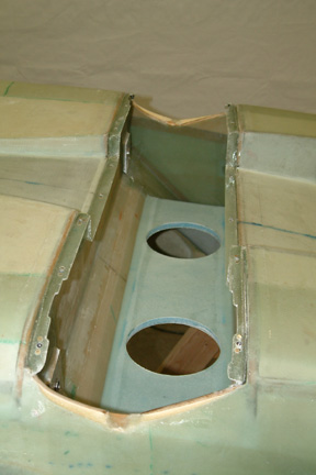 I
marked out 16 locations for nut plates and screws for the cover and drilled them
out with appropriate holes & countersinks. I used the same screws that were
called out by the plans and selected the matching nut plates (MS21069-L3) for
them. It is advisable to buy a rivet squeezer for the job. I ended up using two
flat squeeze heads due to limited access space, but it worked out OK.
I
marked out 16 locations for nut plates and screws for the cover and drilled them
out with appropriate holes & countersinks. I used the same screws that were
called out by the plans and selected the matching nut plates (MS21069-L3) for
them. It is advisable to buy a rivet squeezer for the job. I ended up using two
flat squeeze heads due to limited access space, but it worked out OK.