 First,
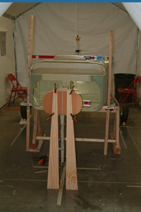
I made sure my fuselage was level fore and aft as well as side to side. Since my
main gear is still attached to the fuselage, all I need to do is to find a way
to raise the front of the fuselage until it is level with the rear. I clamped a
couple of 2x4's along both sides of the fuselage and 1 across & under the
fuselage. With the help of a digital level, I got the fuselage leveled as needed.
First,
I made sure my fuselage was level fore and aft as well as side to side. Since my
main gear is still attached to the fuselage, all I need to do is to find a way
to raise the front of the fuselage until it is level with the rear. I clamped a
couple of 2x4's along both sides of the fuselage and 1 across & under the
fuselage. With the help of a digital level, I got the fuselage leveled as needed.
Note the saw horse under the fuselage is my fail safe support, in case the C-clamps decide to give out. So far, they have been holding up OK.
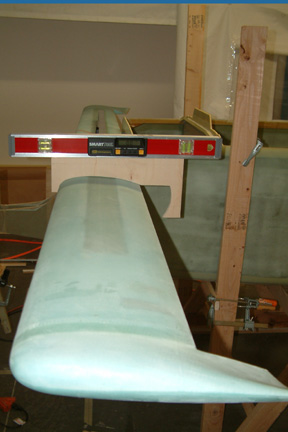
Once the fuselage was leveled, I placed the 12' canard over F-22, it was 0.1 degree off - with the starboard side low. That was easy... a 1/16" washer took care of the problem.
 After
searching through the archives, G template is the template of choice for setting the canard
incidence - no problem there. However, the original G template from drawing M-18
is not the correct one. A 'modified' G template was released with Newsletter #80. Well, I did not have
Newsletter #80 and the modified G template was not available at the 'Unofficial
Cozy Site'. I called Aircraft Spruce and the person who knew anything about the
Cozy Newsletter (Renee) was on maternity leave. I asked for alternate support
and was disappointed to get one of those "I have no idea, just have to wait
till she gets back" type answer. I posted a request to the Forum and
received an original copy as well as a scan-in version of the template two days
later (within hours apart).
After
searching through the archives, G template is the template of choice for setting the canard
incidence - no problem there. However, the original G template from drawing M-18
is not the correct one. A 'modified' G template was released with Newsletter #80. Well, I did not have
Newsletter #80 and the modified G template was not available at the 'Unofficial
Cozy Site'. I called Aircraft Spruce and the person who knew anything about the
Cozy Newsletter (Renee) was on maternity leave. I asked for alternate support
and was disappointed to get one of those "I have no idea, just have to wait
till she gets back" type answer. I posted a request to the Forum and
received an original copy as well as a scan-in version of the template two days
later (within hours apart).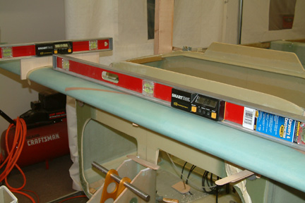 I
laid the modified G template over the original template to determine the
difference. The height of the forward edge was decreased by .3", everything
else remains the same. In other words, put a mark 0.3" below the top left
corner of the original template and draw a straight line joining this 'new' mark
to the top right corner of the template. This equated to a 1.15 degree increase
to the canard incidence. I made a 1/2" thick wooden G template with the new
dimensions and added stir sticks (shims) to the front edge of the canard until
the digital level on the top of the G template registered 0.0 degree. As shown,
the canard is leveled side to side, and 0.0 degree incidence.
I
laid the modified G template over the original template to determine the
difference. The height of the forward edge was decreased by .3", everything
else remains the same. In other words, put a mark 0.3" below the top left
corner of the original template and draw a straight line joining this 'new' mark
to the top right corner of the template. This equated to a 1.15 degree increase
to the canard incidence. I made a 1/2" thick wooden G template with the new
dimensions and added stir sticks (shims) to the front edge of the canard until
the digital level on the top of the G template registered 0.0 degree. As shown,
the canard is leveled side to side, and 0.0 degree incidence. 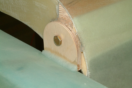 I
made the alignment tabs out of .25" birch wood - just because I feel it
has more substance to it (though the plan suggests Clark foam is OK as well). I
drilled the alignment holes and trimmed them to length.
I
made the alignment tabs out of .25" birch wood - just because I feel it
has more substance to it (though the plan suggests Clark foam is OK as well). I
drilled the alignment holes and trimmed them to length.