Chapter
13 - Section 2
Fabrication
of NG-30
Reinforcing the Glass
Strut
Fabricating
NG-30
Installing
Worm Drive Assembly
Box
Assembly
Nose
Floor & Sides
Rudder
Pedals Master
Brake Cylinders
Completing
Nose Gear
Pitot
& Static System
Closing
the Top Nose
Door
In
this section, I will be fabricating the side panels (NG-30). I did not follow
the plan sequence exactly because some of the alignment requirements can be
achieved easier with techniques we learned from previous chapters.
Cutting
Out the Foam Pieces
I
started out by cutting up a piece of foam large enough for both sides of the
NG-30. I glassed one side of the foam panel (4 ply), peel plied and let cure
overnight. The next day, I cut the foam panel into 2 equal sides. Then I stacked
them on top of each other, glass to glass.
|
 I
traced out the shape of NG-30 on a piece of paper from M-10, M11 and M19. I used
this as a template and transferred the shape of NG-30 onto the foam using my rolling
wheel method. Once transferred, I removed the paper and connected up the
indented dots with a thin line marker. I
traced out the shape of NG-30 on a piece of paper from M-10, M11 and M19. I used
this as a template and transferred the shape of NG-30 onto the foam using my rolling
wheel method. Once transferred, I removed the paper and connected up the
indented dots with a thin line marker.
Note
the 2 screws I put at strategic locations (through the foam/glass/glass/foam
layers) so that I can keep them together without shifting around. Then I cut
out the NG-30 set with my band saw - tightly along the lines. This way, both
sides of the panel will be exactly the same. While the pair is still in tact, I
took a hard block and touched up the imperfections.
Since
I am using Jack Welhelmson's electric landing gear, I only needed three holes (on
both panels) instead of four holes in one panel and three on the other per plan.
However, I have not received Jack's landing gear yet, I decided to hold off
drilling the required holes.
Note
I also left out the 2 holes for the rudder pedals because I plan on using the
hanging rudder pedals instead of the plans pedals.
|
Fabricating
the Doublers
The
bill of materials in Chapter 13 did not call out for Birch plywood and I did not
have any left from previous chapters. I have to make an extra trip for the plywood. The doublers were straight forward. I cut them up with the table saw and
put in the 45o bevels per plan.
| Fabricating
the Aluminum Insert and Doublers |
|
 After
I cut up the NG-30 foam/glass layers with my band saw, it wouldn't do much with
aluminum. I ended up changing to a new bi-metal blade. Just have to save the old
one for fiber glass only. I cut up the aluminum inserts and the doublers with
little problem. After
I cut up the NG-30 foam/glass layers with my band saw, it wouldn't do much with
aluminum. I ended up changing to a new bi-metal blade. Just have to save the old
one for fiber glass only. I cut up the aluminum inserts and the doublers with
little problem.
The
plan called for 45o bevels on the 1/8" aluminum doublers - all
4 sides. I tilted my belt sander table to 45o and sanded the edges
of the doublers down to the
bevels as required. It turned out nicely - I was actually pleasantly
surprised. The only challenge with this approach was - How loooooong can you
hang onto the doublers before your fingerprints get totally erased by the
heat... and I need to get down to DMV to renew my drivers license in the next
few days  . .
|
|
 After
my fingers tips cooled off, I cut a couple square holes on the birch wood
doublers and floxed the 1/4" aluminum inserts in place. After
my fingers tips cooled off, I cut a couple square holes on the birch wood
doublers and floxed the 1/4" aluminum inserts in place.
|
| Glassing
the MKNG-6 Pivot |
|
 I
made a paper template for the MKNG-6 pivot peel ply and glassing dimensions
per plan and traced them out onto NG-30. Then I followed the rest of the effort
per plan. Note the big white hole I filled with micro at the bottom left edge -
that was one of the 2 'strategic' nail locations I used to hold the 2 NG-30
together...so much for strategic locations!!! I
made a paper template for the MKNG-6 pivot peel ply and glassing dimensions
per plan and traced them out onto NG-30. Then I followed the rest of the effort
per plan. Note the big white hole I filled with micro at the bottom left edge -
that was one of the 2 'strategic' nail locations I used to hold the 2 NG-30
together...so much for strategic locations!!!
|
Jack
Wilhelmson's Mounting Bracket and its Mystery Holes
Jack's
instructions on the three (3) holes needed for his actuator brackets are kind of
vague. The bracket came with the far forward hole pre-drilled and it mounts in
the second hole back in the NG-30'. I went to M-10 and found the 4 holes for
MG-51 (2 at the bottom end, 1 at the middle and one at top of the part). Since I
did not order NG-51, the M-10 drawing was my only documentation for the part. I
transferred the locations of the 3 holes needed (shown in M-10, ie. the top,
middle & second from the bottom) and put a 1/16" hole through the NG-30
just for reference. I did not put in the #12 holes yet because I have not
received Jack's parts.
By
the time I was ready to remove the foam for the hard points, I decided to look
through other web sites and noticed my hole locations did not have the same
offset to each other, I was puzzled. Meanwhile, a couple e-mails
appeared in the Cozy forum complaining about the lack of information as to where
those hole locations should be for the new builders instead of retrofitters.
Evidently, a few of the new builders put in their hard points and found out they
were in the wrong locations. I revisited all the web sites and no one really
talked about how they determined the correct hole locations and their center hole
had a different offset than mine. Now, I knew I got the wrong hole and I was
really confused...
|
 After
some thorough searching, I realized where the confusion was. The four holes the
plans refer to are shown in Chapter 13, page 3, the hole that is needed in only
one side on the NG-30 (fig 8) is not shown in M-10!!! It is, however, shown in
Chapter 13 Page 3. Fortunately, the NG-51 is in full scale in Chapter 13 page 3,
so I can transfer the missing hole to my M-10 drawing. The center hole (the
3/4" diameter) is the misleading hole. Once I caught that, it was clear. I
just have to plug an old 1/16" hole and put a new one in. That was
close... After
some thorough searching, I realized where the confusion was. The four holes the
plans refer to are shown in Chapter 13, page 3, the hole that is needed in only
one side on the NG-30 (fig 8) is not shown in M-10!!! It is, however, shown in
Chapter 13 Page 3. Fortunately, the NG-51 is in full scale in Chapter 13 page 3,
so I can transfer the missing hole to my M-10 drawing. The center hole (the
3/4" diameter) is the misleading hole. Once I caught that, it was clear. I
just have to plug an old 1/16" hole and put a new one in. That was
close...
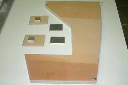
Here's
a picture where I floxed in the doubler onto the NG-30. If you look close, you
can also see the 'new found' hole locations for the hard points.
|
| Hard
Points |
|
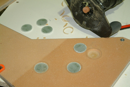 Once
the hole locations were established, I was required to build up six 1.2"
diameter 15 plies BID hard points. I laid up a 15 ply, 4"x6" BID and
let cure overnight. You can see the cured BID in the above picture. Then I used a 1.5" carbide grit hole saw and cut out
six round discs (hard points). Since the hole saw has a thick wall, I ended up with
~1.33" diameter discs. I took one of these discs and traced them out on the
NG-30 foam surface, centered at each of the six hole locations. With a Dremel and
a grinding stone bit, I removed the foam for the hard points and floxed them in. I rounded off the
edges around the hard points and am now ready for surface glassing. Once
the hole locations were established, I was required to build up six 1.2"
diameter 15 plies BID hard points. I laid up a 15 ply, 4"x6" BID and
let cure overnight. You can see the cured BID in the above picture. Then I used a 1.5" carbide grit hole saw and cut out
six round discs (hard points). Since the hole saw has a thick wall, I ended up with
~1.33" diameter discs. I took one of these discs and traced them out on the
NG-30 foam surface, centered at each of the six hole locations. With a Dremel and
a grinding stone bit, I removed the foam for the hard points and floxed them in. I rounded off the
edges around the hard points and am now ready for surface glassing.
[Hindsight:
You may want to read forward to Section 3 of this Chapter - under Timing
is Everything]
|
| Details...Details... |
|
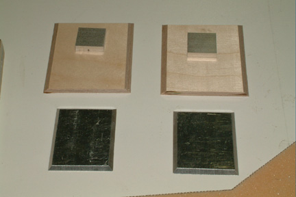
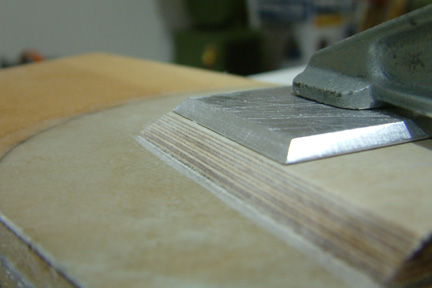 I
caught a couple notable recommendations from other builders. The first one was
from Wayne Hicks' site where he suggested beveling the birch and aluminum doubler
for the NG-6 at the same time. Since I cut my birch bevel with my table saw and
the aluminum bevel with my belt sander, I decided to check its alignment
prior to its subsequent glassing operation. Luckily, they were pretty close...
but I had to do some fine sanding to make it right. I
caught a couple notable recommendations from other builders. The first one was
from Wayne Hicks' site where he suggested beveling the birch and aluminum doubler
for the NG-6 at the same time. Since I cut my birch bevel with my table saw and
the aluminum bevel with my belt sander, I decided to check its alignment
prior to its subsequent glassing operation. Luckily, they were pretty close...
but I had to do some fine sanding to make it right.
[Hindsight:
I had a tough time glassing over the metal plate edges because I did not round off
the sharp edges at the top. I have to clamp everything down for cure.]
|
NG-30
Reinforcement
The
second recommendation was from an e-mail between Jack Wilhelmson and Nat Puffer
after Jack's nose gear collapsed into an 8" hole. It was expressed by Nat
(later in one of the newsletters) that it may be a good idea to add a couple more plies of BID (preferably UND) at
the thinnest point of NG-30. I do not think there was an official plans change
requirement. Since I am right at this point, I decided to add the plies as
recommended. I got a chance to talk to Jack prior to adding the reinforcement.
He recommended that I add a 3" radius at the elbow and 2 layers of UND (to
the NG-30) horizontally.
|
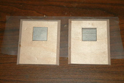
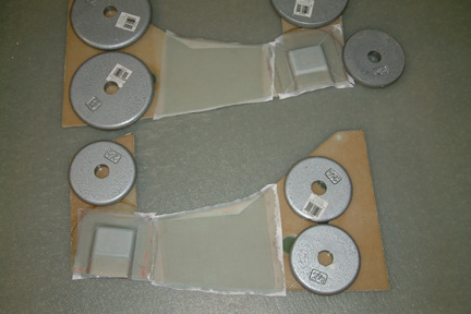 I
felt the 3" radius at the elbow corner was a bit small, so I decided to
extend it further to give a larger surface for the UND reinforcement. My UND
reinforcement starts 1/2" forward of the forward most hard point and ends
~6" forward of the elbow. I shaped and microed a foam radius between those two
points (as shown). I added 3 layers of UND (horizontally) on both sides of the
NG-30. I weighed down the NG-30 to make sure they stay flat. From the lessons
learned above, I rounded off the sharp edges on the top of the second metal bracket and the
glass laid down nicely. I also peel plied all surfaces. I
felt the 3" radius at the elbow corner was a bit small, so I decided to
extend it further to give a larger surface for the UND reinforcement. My UND
reinforcement starts 1/2" forward of the forward most hard point and ends
~6" forward of the elbow. I shaped and microed a foam radius between those two
points (as shown). I added 3 layers of UND (horizontally) on both sides of the
NG-30. I weighed down the NG-30 to make sure they stay flat. From the lessons
learned above, I rounded off the sharp edges on the top of the second metal bracket and the
glass laid down nicely. I also peel plied all surfaces.
|
| Carving
Out the NG-6 Cavity |
|
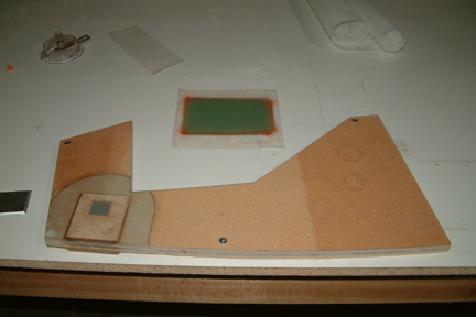
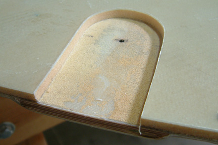 Once
the UND was cured, I turned the NG-30 over and carved out the NG-6 per plan. I
first used a router to remove most of the glass and foam. I
removed the rest of the foam with a Dremel, exposing the peel ply underneath (as shown). After
I removed the peel ply, I added a 45o slope to the foam and glassed
per plan. Once
the UND was cured, I turned the NG-30 over and carved out the NG-6 per plan. I
first used a router to remove most of the glass and foam. I
removed the rest of the foam with a Dremel, exposing the peel ply underneath (as shown). After
I removed the peel ply, I added a 45o slope to the foam and glassed
per plan.
|