 One
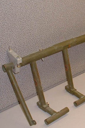
of those deviations is how I attach my rudder cable to the pedals. The Velocity
pedals have two outer most arms (besides the 4 foot pedals) for attaching the
rudder cables (shown left) . Initially, I built the two outer arms as well.
Eventually, I realized I did not need those outermost arms if I find a way to tie
the rudder cables directly to the foot pedal arms (recall my foot pedal arms
have 5 large holes down each arm). Solution was not too far out of reach...
One
of those deviations is how I attach my rudder cable to the pedals. The Velocity
pedals have two outer most arms (besides the 4 foot pedals) for attaching the
rudder cables (shown left) . Initially, I built the two outer arms as well.
Eventually, I realized I did not need those outermost arms if I find a way to tie
the rudder cables directly to the foot pedal arms (recall my foot pedal arms
have 5 large holes down each arm). Solution was not too far out of reach...
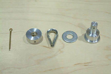 My
rudder cable attachments consist of a cotter pin, 2 small lathe parts (a plug
and a bushing), a washer
(which turned into a thicker bushing/washer later on), and a cable thimble. I
was happy how these parts turned out - I made them with my mini-lathe.
My
rudder cable attachments consist of a cotter pin, 2 small lathe parts (a plug
and a bushing), a washer
(which turned into a thicker bushing/washer later on), and a cable thimble. I
was happy how these parts turned out - I made them with my mini-lathe.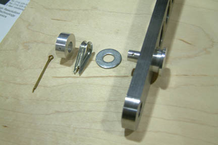 I
took advantage of the holes in the rudder pedal arms for anchoring the cable
attachment (and later on, the master cylinder). Here's how they are arranged
when attaching to my rudder arms instead of the outer arms. The 'plug' goes
through the lowest hole in the pedal arm while the other parts stack through its
post.
I
took advantage of the holes in the rudder pedal arms for anchoring the cable
attachment (and later on, the master cylinder). Here's how they are arranged
when attaching to my rudder arms instead of the outer arms. The 'plug' goes
through the lowest hole in the pedal arm while the other parts stack through its
post. 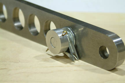
 Normally,
the pedal is positioned all the way against the side wall to the right. I moved
it out so that I could take the picture and show its connections. I also plan on
mounting a turnbuckle in line with the cable so that I can keep the cable taut.
This way, I can eliminate the outer most arms and reduce a bit of weight in the
process... I was pretty happy with the
result
Normally,
the pedal is positioned all the way against the side wall to the right. I moved
it out so that I could take the picture and show its connections. I also plan on
mounting a turnbuckle in line with the cable so that I can keep the cable taut.
This way, I can eliminate the outer most arms and reduce a bit of weight in the
process... I was pretty happy with the
result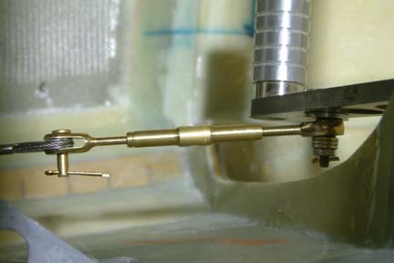 OK,
Jamie gave me some ideas and I followed his recommendation. I used a similar rudder
cable mounting concept (as above) but added the turnbuckle directly to the
'plug post' at the rudder pedal arm (left). The cable thimble is moved to the
trailing end of the turnbuckle. This
way, I can get the cable in close proximity, then tighten it by turning
the turnbuckle. Notice my cotter pin is a bit too long (in the picture) - they
will be replaced with more appropriate length ones.
OK,
Jamie gave me some ideas and I followed his recommendation. I used a similar rudder
cable mounting concept (as above) but added the turnbuckle directly to the
'plug post' at the rudder pedal arm (left). The cable thimble is moved to the
trailing end of the turnbuckle. This
way, I can get the cable in close proximity, then tighten it by turning
the turnbuckle. Notice my cotter pin is a bit too long (in the picture) - they
will be replaced with more appropriate length ones.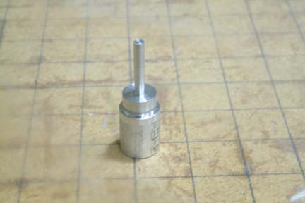 With
the re-design, I did not like the mounting post as part of the 'plug' (above)
because I have to turn it down to 3/8" in diameter to accommodate the
attachment hole of the turnbuckle. Its kind of skinny and I felt it had a remote possibility of breaking off - though the pull force on
the rudder is minimal. But then, losing rudder control in the air is not a trivial
problem...
With
the re-design, I did not like the mounting post as part of the 'plug' (above)
because I have to turn it down to 3/8" in diameter to accommodate the
attachment hole of the turnbuckle. Its kind of skinny and I felt it had a remote possibility of breaking off - though the pull force on
the rudder is minimal. But then, losing rudder control in the air is not a trivial
problem...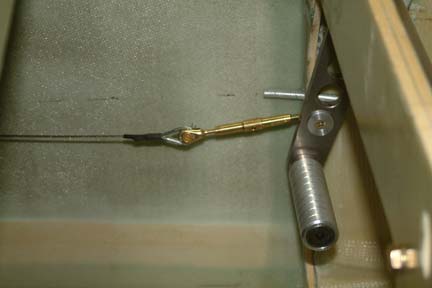 I decided to use a through bolt (AN3)
in place of the post. This way, the bolt has to be completely sheared off before
losing
my rudder cable connection.
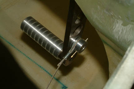
If you look close, you
can see the through hole & bolt I added through the plug. Note the rudder
arm is ~12.9o aft from vertical per plan.
I decided to use a through bolt (AN3)
in place of the post. This way, the bolt has to be completely sheared off before
losing
my rudder cable connection.
If you look close, you
can see the through hole & bolt I added through the plug. Note the rudder
arm is ~12.9o aft from vertical per plan.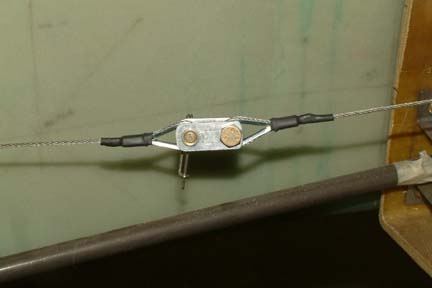 Don't
forget the quick disconnect behind the firewall. Note I added shrink sleeving to
all my cable terminations, just to keep the dirt out.
Don't
forget the quick disconnect behind the firewall. Note I added shrink sleeving to
all my cable terminations, just to keep the dirt out.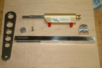 Here
are the parts I made for activating the master cylinder yet provide free travel for
the rudder cable. I have seen somewhat of a similar concept in the
past, but cannot re-locate it anymore. Therefore, whoever it is - thanks for the
idea!
Here
are the parts I made for activating the master cylinder yet provide free travel for
the rudder cable. I have seen somewhat of a similar concept in the
past, but cannot re-locate it anymore. Therefore, whoever it is - thanks for the
idea!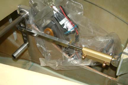 As
shown in the assembly (left), the foot pedal is pulled back ~17.5o
from vertical at neutral position. This is being pulled back by the turnbuckle
from the rudder cable pedal. As the foot pedal is pushed forward (engaging the
rudder) for 17.5o (which equates to the ~4.2" rudder swing per
plan), my foot pedal will be at vertical position. During this time, the steel pin
will merely travel along the slot of the square rod.
As
shown in the assembly (left), the foot pedal is pulled back ~17.5o
from vertical at neutral position. This is being pulled back by the turnbuckle
from the rudder cable pedal. As the foot pedal is pushed forward (engaging the
rudder) for 17.5o (which equates to the ~4.2" rudder swing per
plan), my foot pedal will be at vertical position. During this time, the steel pin
will merely travel along the slot of the square rod. 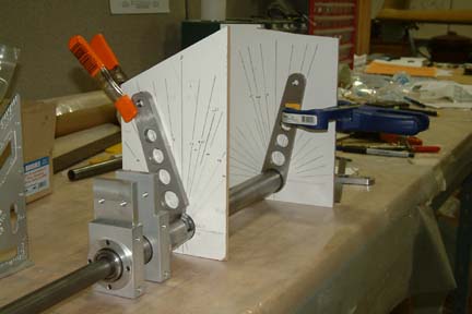 Based
on my calculations in Chapter 16 - Section 6, my pedal swing is -17.5o
to +17.5o. To verify my calculations with the actual part, I lay the entire rudder pedal set upside down on the work
bench nicely. I made two (2) wood templates with angles drawn - radiating from
the center of the outer tube as shown. Now I can move the pedal arms back and
forth - while I can lengthen the slot (or narrow down the pedal arm) a bit at a
time. When I was done, I have ~1/8" clearance on each side of the pedal arm
- which equate to additional rudder swing if needed or possible.
Based
on my calculations in Chapter 16 - Section 6, my pedal swing is -17.5o
to +17.5o. To verify my calculations with the actual part, I lay the entire rudder pedal set upside down on the work
bench nicely. I made two (2) wood templates with angles drawn - radiating from
the center of the outer tube as shown. Now I can move the pedal arms back and
forth - while I can lengthen the slot (or narrow down the pedal arm) a bit at a
time. When I was done, I have ~1/8" clearance on each side of the pedal arm
- which equate to additional rudder swing if needed or possible.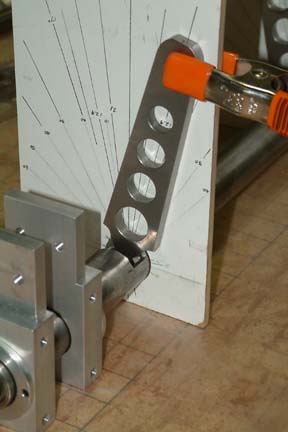 Here's
another view of the slot length and clearance...
Here's
another view of the slot length and clearance...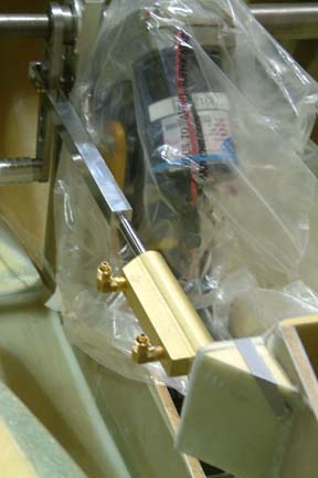 Since
my master cylinders are mounted on both sides of NG-30, their hard point
locations are somewhat obvious. The only unknown is its height position.
Since
my master cylinders are mounted on both sides of NG-30, their hard point
locations are somewhat obvious. The only unknown is its height position.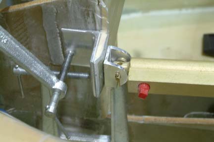 Once
I figured out the optimal location (minimum push force) of the attach point, I
trimmed the faceplate size to minimum. In addition, I just did not like the looks
of the 45o glass support for the face plate (above picture) and decided to replace it with
an angle bracket as shown.
Once
I figured out the optimal location (minimum push force) of the attach point, I
trimmed the faceplate size to minimum. In addition, I just did not like the looks
of the 45o glass support for the face plate (above picture) and decided to replace it with
an angle bracket as shown.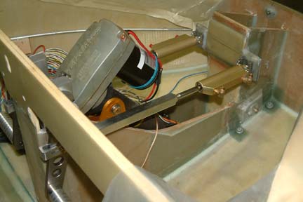 After
glassing the angle support, the master cylinders are re-mounted. The only thing I need to add is
the reservoirs
After
glassing the angle support, the master cylinders are re-mounted. The only thing I need to add is
the reservoirs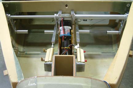 I
disassembled the unit, took it to an aircraft welding shop and tig welded the
rudder pedal arms onto the hanging tubes - being very careful with its alignment
and positions. With all the jigging and welding, it took about 30 minutes. I
took it home, cleaned off the weld marks with Scott Bright and painted it silver.
With the turnbuckle taut, I can bring the foot pedal quite a ways
back - for the shorter pilots...
I
disassembled the unit, took it to an aircraft welding shop and tig welded the
rudder pedal arms onto the hanging tubes - being very careful with its alignment
and positions. With all the jigging and welding, it took about 30 minutes. I
took it home, cleaned off the weld marks with Scott Bright and painted it silver.
With the turnbuckle taut, I can bring the foot pedal quite a ways
back - for the shorter pilots...