 The
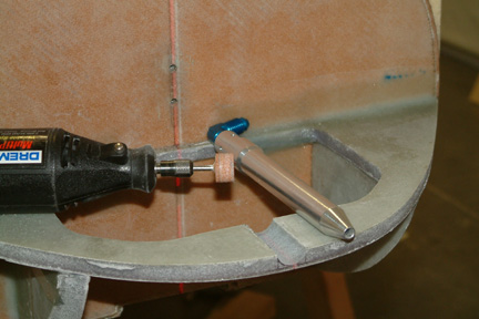
pitot tube per the drawing construction method is pretty flimsy and I prefer a
more beefy one. There were plenty of discussion on the Cozy Forum regarding
alternatives. I liked the one Wayne Hicks used and I ended up getting the same from
Aircraft Spruce ($27). I marked the pitot tube extension location at the nose carefully
with my lasers and opened it up with a drill and Dremel grinding wheel.
Since the pitot tube is husky and I plan to extend the tube out the nose by 1
1/2" only, I see no reason to make it removable. Hence, I put a groove
onto NG-31 such that I can seat and flox the pitot tube in place. I will eventually
have to cut the pitot tube shorter and put a thread at the cut end for the fitting. The picture
showed the original pitot tube and the groove on NG-31.
The
pitot tube per the drawing construction method is pretty flimsy and I prefer a
more beefy one. There were plenty of discussion on the Cozy Forum regarding
alternatives. I liked the one Wayne Hicks used and I ended up getting the same from
Aircraft Spruce ($27). I marked the pitot tube extension location at the nose carefully
with my lasers and opened it up with a drill and Dremel grinding wheel.
Since the pitot tube is husky and I plan to extend the tube out the nose by 1
1/2" only, I see no reason to make it removable. Hence, I put a groove
onto NG-31 such that I can seat and flox the pitot tube in place. I will eventually
have to cut the pitot tube shorter and put a thread at the cut end for the fitting. The picture
showed the original pitot tube and the groove on NG-31.
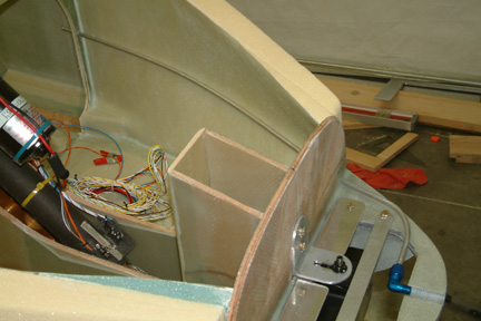 I
cut the 1/4" aluminum tubing from Aircraft Spruce to 38" & 6"
per plan. Then I drilled the necessary holes through F-0 and F-22 and threaded the
tubing up hill along the left side wall. The tubing was easy to bend. I just
bent it by hand and it hugs along the side wall readily. I had to get a flaring
tool (McMaster-Carr) to connect the tubing to the blue fitting. I hope we will be
using a lot of tubing down the road because the flaring tool set me back $90+
for one shot ... so far.
I
cut the 1/4" aluminum tubing from Aircraft Spruce to 38" & 6"
per plan. Then I drilled the necessary holes through F-0 and F-22 and threaded the
tubing up hill along the left side wall. The tubing was easy to bend. I just
bent it by hand and it hugs along the side wall readily. I had to get a flaring
tool (McMaster-Carr) to connect the tubing to the blue fitting. I hope we will be
using a lot of tubing down the road because the flaring tool set me back $90+
for one shot ... so far. 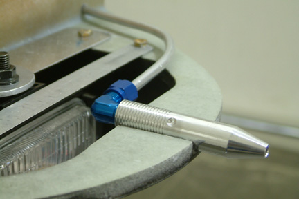 Here's
a close look of the pitot tube after Jamie cut it to length and threaded it for
the fitting. Jamie owns a machine shop close by and he had been providing
machining support for us for the past 16 years. I have gained tremendous amount
of knowledge in material properties and its machining processes from him - a
very talented person. He also helped me with my rudder pedals in Section 6 of
the Chapter. You can see Jamie can get a bit artistic with his work sometime
Here's
a close look of the pitot tube after Jamie cut it to length and threaded it for
the fitting. Jamie owns a machine shop close by and he had been providing
machining support for us for the past 16 years. I have gained tremendous amount
of knowledge in material properties and its machining processes from him - a
very talented person. He also helped me with my rudder pedals in Section 6 of
the Chapter. You can see Jamie can get a bit artistic with his work sometime 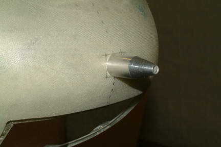 Pitot tube extending out the center of the nose cone.
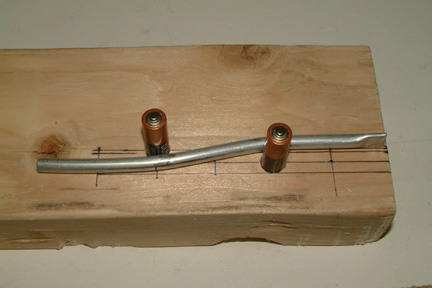 The
6" aluminum tube cut earlier is for the static port. I pinched one end of
the tube with my rivet squeezer (it worked well). I made a simple bending
fixture and bent the aluminum tubing to shape.
The
6" aluminum tube cut earlier is for the static port. I pinched one end of
the tube with my rivet squeezer (it worked well). I made a simple bending
fixture and bent the aluminum tubing to shape.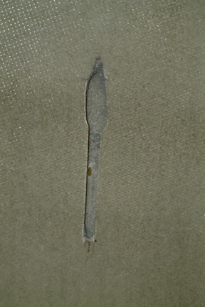 Instead,
I took the Fein tool and cut a strip of the glass out, dug out the foam and was ready to bury the static tube in a matter of 15 minutes. The wider hole at the top part was from the 1/4" drill bit and the lower
straight part was from the FEIN tool. See that small hole I put on the outside
wall with the tip of my 1/4" drill bit - at the middle?
Instead,
I took the Fein tool and cut a strip of the glass out, dug out the foam and was ready to bury the static tube in a matter of 15 minutes. The wider hole at the top part was from the 1/4" drill bit and the lower
straight part was from the FEIN tool. See that small hole I put on the outside
wall with the tip of my 1/4" drill bit - at the middle?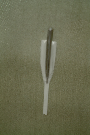 I
marked the pitot tube position on the outside of the fuselage (with the help of
a flash light), made some wet and drier micro. I partially filled the cut out
with wet micro first, then I inserted the aluminum tube, making sure it is set
tightly against the outside wall of the fuselage. Then I sealed the rest of the
slot with the drier micro. Once it cures, I patched it up with 2 BIDs of glass and all
is well.
I
marked the pitot tube position on the outside of the fuselage (with the help of
a flash light), made some wet and drier micro. I partially filled the cut out
with wet micro first, then I inserted the aluminum tube, making sure it is set
tightly against the outside wall of the fuselage. Then I sealed the rest of the
slot with the drier micro. Once it cures, I patched it up with 2 BIDs of glass and all
is well. 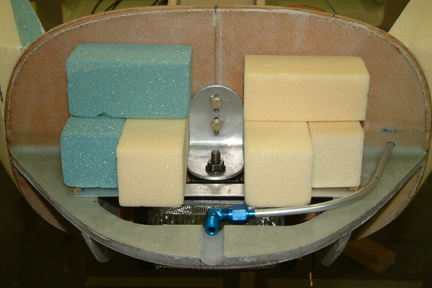 I
also learned that lead is ~0.41 lb / cu. in. The 32 lbs can be in the form of a
bag of lead pallets or in a 2" x2"x19.5" block. Since my nose cone
door and space would not allow a 20" long block, I just have to make
shorter blocks. I cut up a bunch of 2"x2"foam blocks and did a trial
fit. The 4 longer blocks are 2"x2"x4" and the shorter ones are
2"x2"x3". I can fit 22" of blocks that equates
to ~ 36 lbs of ballast. - giving me a small margin of flexibility - just
in case I lose some more weight
I
also learned that lead is ~0.41 lb / cu. in. The 32 lbs can be in the form of a
bag of lead pallets or in a 2" x2"x19.5" block. Since my nose cone
door and space would not allow a 20" long block, I just have to make
shorter blocks. I cut up a bunch of 2"x2"foam blocks and did a trial
fit. The 4 longer blocks are 2"x2"x4" and the shorter ones are
2"x2"x3". I can fit 22" of blocks that equates
to ~ 36 lbs of ballast. - giving me a small margin of flexibility - just
in case I lose some more weight 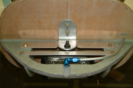 As
noted above, the removable 'floor' over the landing light access hole consists of
two aluminum strips mounted across the landing light access hole. The 3/4"
and 1 1/2" wide aluminum strips
are being held down by 4 bolts and nut plates built into the NG-31 floor. I had
to notch out the wider strip to fit under the L bracket to provide some freedom
for the landing light. An alternative is a wire mesh / net of some kind... if
I come across something better. If I stay with the aluminum strip approach, I
will drill a few holes through the aluminum strips and up through the lead blocks, stick a
long threaded bolt through them (vertically) and secure the whole assembly with a
wing nut at the
top. That will keep them somewhat secure during flight. I also added a nut plate
on the top of F-0. This will be used to hold an L bracket, which in turn holds
the top end of the threaded bolts for the ballast.
As
noted above, the removable 'floor' over the landing light access hole consists of
two aluminum strips mounted across the landing light access hole. The 3/4"
and 1 1/2" wide aluminum strips
are being held down by 4 bolts and nut plates built into the NG-31 floor. I had
to notch out the wider strip to fit under the L bracket to provide some freedom
for the landing light. An alternative is a wire mesh / net of some kind... if
I come across something better. If I stay with the aluminum strip approach, I
will drill a few holes through the aluminum strips and up through the lead blocks, stick a
long threaded bolt through them (vertically) and secure the whole assembly with a
wing nut at the
top. That will keep them somewhat secure during flight. I also added a nut plate
on the top of F-0. This will be used to hold an L bracket, which in turn holds
the top end of the threaded bolts for the ballast.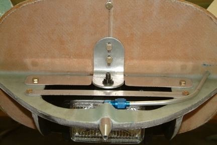 Here's
a picture of the pitot tube floxed in place. I also sealed off the hole at F-0
where the aluminum goes through with silicon sealant.
Here's
a picture of the pitot tube floxed in place. I also sealed off the hole at F-0
where the aluminum goes through with silicon sealant.