 My
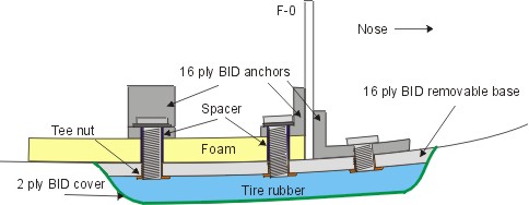
nose bumper will consist of a 16 ply BID base (like the sole of a shoe),
which will be shaped to the curvature of the fuselage for good contact against
shear forces. This BID
base will be bolted tightly to the bottom of the nose & fuselage with (5)
T-nuts and 1/4" bolts. It can be removed for repair after a gear up landing
or whatever reason. The 5 anchors (for the bolts) are made out of a set of
16 BID 'L' brackets, epoxied against the sides of F-0 and NG-30 respectively. I
got this idea from reading Wayne Hick's site (BTW, he's got a gorgeous looking
nose bumper). A
bullet shaped 1/2" thick rubber bumper will be floxed onto the BID base
(taken from Bill's approach). The entire contraption will be enclosed by 2 BID
plies, like the upper cover of a shoe. This 2 ply BID serves two purposes - 1) It covers up the rubber tire
material so that the bumper looks like it is part of the plane and 2) It
provides additional enforcement to keep the rubber from peeling off (in addition
to the flox surface).
My
nose bumper will consist of a 16 ply BID base (like the sole of a shoe),
which will be shaped to the curvature of the fuselage for good contact against
shear forces. This BID
base will be bolted tightly to the bottom of the nose & fuselage with (5)
T-nuts and 1/4" bolts. It can be removed for repair after a gear up landing
or whatever reason. The 5 anchors (for the bolts) are made out of a set of
16 BID 'L' brackets, epoxied against the sides of F-0 and NG-30 respectively. I
got this idea from reading Wayne Hick's site (BTW, he's got a gorgeous looking
nose bumper). A
bullet shaped 1/2" thick rubber bumper will be floxed onto the BID base
(taken from Bill's approach). The entire contraption will be enclosed by 2 BID
plies, like the upper cover of a shoe. This 2 ply BID serves two purposes - 1) It covers up the rubber tire
material so that the bumper looks like it is part of the plane and 2) It
provides additional enforcement to keep the rubber from peeling off (in addition
to the flox surface).
[Hindsight:
I added an aluminum spacer (tube) between the 16 BID anchor and the 16 ply BID
base to prevent compression of the foam when tightening the bolts. More
discussion 2 paragraphs below.]
In
the event of a gear up landing, the very top part of the 2 ply BID will make contact
and I suspect, it will last about 2 seconds, then the tire will hit the road. However, most of the surrounding 2
plies should remain in place. Since the rubber is secured to the 16 ply BID by flox as well as the remaining 2 BID glass enclosure, it should stay
put. As there is no bolt protruding above the rubber, the grinding will have to
take 1/2" of tire rubber before reaching my second and third line of
defense (i.e. the nose strut plate and the 16 ply BID. I plan to strengthen
the nose strut skid plate either with SS or maple wood.
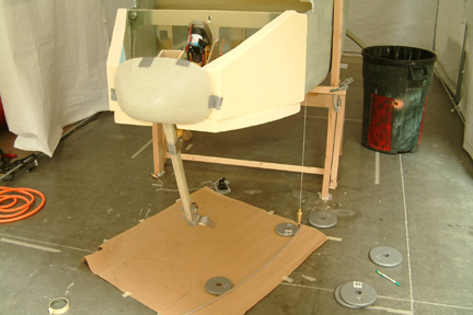 First,
I make sure the fuselage is leveled from side to side and front and back. Then I
firmly attached the nose cone that I purchased from FeatherLite to F-0
with duct tape. I taped a large piece of paper on the floor underneath the nose.
Using a plumb line, I marked several data points on the paper along the
curvature of the fuselage before the foam. I repeated the process with the data
points along the edge of the nose cone. Then I connected the data points with a
long flexible aluminum strip as shown. This line forms the curvatures of the
nose sides. My next step was to make two wood templates with its edge shaped to
the same curvature.
First,
I make sure the fuselage is leveled from side to side and front and back. Then I
firmly attached the nose cone that I purchased from FeatherLite to F-0
with duct tape. I taped a large piece of paper on the floor underneath the nose.
Using a plumb line, I marked several data points on the paper along the
curvature of the fuselage before the foam. I repeated the process with the data
points along the edge of the nose cone. Then I connected the data points with a
long flexible aluminum strip as shown. This line forms the curvatures of the
nose sides. My next step was to make two wood templates with its edge shaped to
the same curvature. 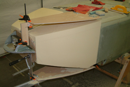 Once
I made the templates, I turned the fuselage over to its up side down position. I
mounted the templates level and parallel to each other as shown. I used clamps
at the front and hot glued at the back to keep the template in place during the
sanding. I definitely do not want them to move on me at this time. The rest is
just sanding the sides with a long sanding block along the template curvatures.
However, I took time with this process because mistakes will be costly down the
road. I repeated the other side with the same approach.
Once
I made the templates, I turned the fuselage over to its up side down position. I
mounted the templates level and parallel to each other as shown. I used clamps
at the front and hot glued at the back to keep the template in place during the
sanding. I definitely do not want them to move on me at this time. The rest is
just sanding the sides with a long sanding block along the template curvatures.
However, I took time with this process because mistakes will be costly down the
road. I repeated the other side with the same approach.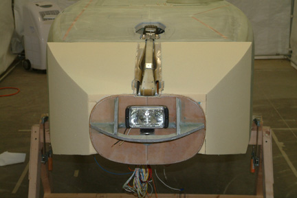 I
removed the NG-5 plate from the top of the strut so that I can sand the bottom
without obstruction. Then I made a couple long and wide sanding blocks for
shaping the bottom. I used the strut cover as a guide for sanding. However,
MKNG-3 gave me a slight problem which I have to do a bit of local sanding. In
the end, it worked out OK. I was surprised how sharp the corners turned out
though.
I
removed the NG-5 plate from the top of the strut so that I can sand the bottom
without obstruction. Then I made a couple long and wide sanding blocks for
shaping the bottom. I used the strut cover as a guide for sanding. However,
MKNG-3 gave me a slight problem which I have to do a bit of local sanding. In
the end, it worked out OK. I was surprised how sharp the corners turned out
though.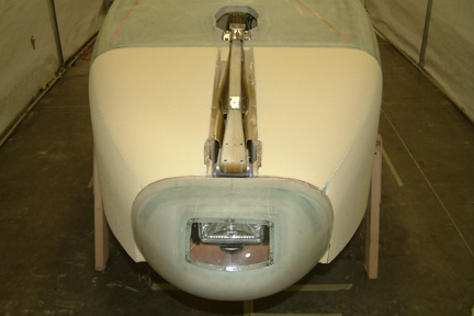 I
contemplated to make a jig to shape the corners but decided against it because
the corner curvature will not be constant from the fuselage to the nose. I
decided to shape it by eye. I made the rough cut with a hacksaw blade. I held
the hack saw blade at both ends (without the hacksaw mounting frame), bent it a
bit and scraped the foam off the corners with long strokes - from nose to
fuselage. Once I got the rough cut, I switched over to the sanding belt I used for
shaping the fuselage bottom sides. Again, with long strokes from front to back
(NOT as polishing your shoes), to smooth out the corners. Its a messy task and
you'll get foam dust all over the place. Fortunately, the foam was so easy to
shape, it took me about 3 hours to complete.
I
contemplated to make a jig to shape the corners but decided against it because
the corner curvature will not be constant from the fuselage to the nose. I
decided to shape it by eye. I made the rough cut with a hacksaw blade. I held
the hack saw blade at both ends (without the hacksaw mounting frame), bent it a
bit and scraped the foam off the corners with long strokes - from nose to
fuselage. Once I got the rough cut, I switched over to the sanding belt I used for
shaping the fuselage bottom sides. Again, with long strokes from front to back
(NOT as polishing your shoes), to smooth out the corners. Its a messy task and
you'll get foam dust all over the place. Fortunately, the foam was so easy to
shape, it took me about 3 hours to complete.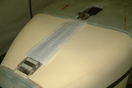 One
of the steps involved in glassing the nose is to cut the strut loose after the
bottom is cured. I was concerned about cutting 'around' the nose cover (from
Featherlite) and that the cut should be symmetrical. Since it would be difficult
to find the cut line afterwards, I decided to make a paper template first. As
shown, I drew a center line down the strut and at every inch, I took an equal
distance left and right from the center line (yet clears the nose cover). Once
done, I joined the dots with a French curve on one side. Then I fold the
template over at the center line and traced out the other
side.
One
of the steps involved in glassing the nose is to cut the strut loose after the
bottom is cured. I was concerned about cutting 'around' the nose cover (from
Featherlite) and that the cut should be symmetrical. Since it would be difficult
to find the cut line afterwards, I decided to make a paper template first. As
shown, I drew a center line down the strut and at every inch, I took an equal
distance left and right from the center line (yet clears the nose cover). Once
done, I joined the dots with a French curve on one side. Then I fold the
template over at the center line and traced out the other
side. 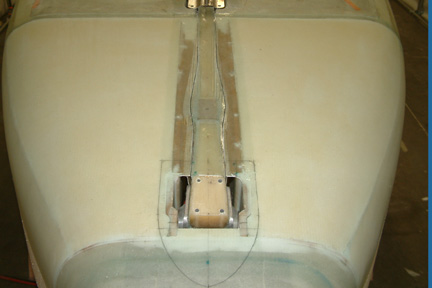 I
laid the glass over the nose bottom and pre-cut the glass (2 layers) prior to
applying micro onto the foam. I also removed NG-5 (but taped over the foot
print) before glassing. I then applied dry micro over the dents and gaps between
the nose cone and F-0. I also taped down the sides per plan as well. I almost
missed the 3rd ply and caught it at the last minute.
I
laid the glass over the nose bottom and pre-cut the glass (2 layers) prior to
applying micro onto the foam. I also removed NG-5 (but taped over the foot
print) before glassing. I then applied dry micro over the dents and gaps between
the nose cone and F-0. I also taped down the sides per plan as well. I almost
missed the 3rd ply and caught it at the last minute.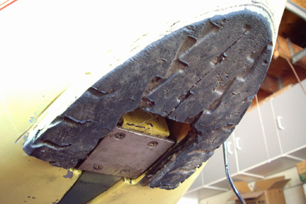 I
sent Bill a private e-mail and asked for specifics. He responded with
clarifications and a picture showing his battle scars (left)! If I remember correctly,
he 'tested' this truck tire contraption 3 times and he thinks it should be good for two
more times. He also stressed that flox worked surprising well in bonding
old tires onto fiber glass. When asked about how to replace the old tire - the
answer was 'I got a monster grinder'! Well the truck tire material makes sense
to me as far as wear resistance to the runway surface is concerned - I am sure
we all had a few hard brakings (or fast starting for the young builders) one time
or another - and above all, his contraption was proven! Thanks Bill, for this
practical idea...
I
sent Bill a private e-mail and asked for specifics. He responded with
clarifications and a picture showing his battle scars (left)! If I remember correctly,
he 'tested' this truck tire contraption 3 times and he thinks it should be good for two
more times. He also stressed that flox worked surprising well in bonding
old tires onto fiber glass. When asked about how to replace the old tire - the
answer was 'I got a monster grinder'! Well the truck tire material makes sense
to me as far as wear resistance to the runway surface is concerned - I am sure
we all had a few hard brakings (or fast starting for the young builders) one time
or another - and above all, his contraption was proven! Thanks Bill, for this
practical idea... 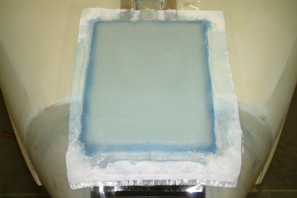 First,
I drew up a bumper base pattern (paper template) similar to Bill's contraption (bullet shape) and
traced it onto the desirable location (2 pictures above). Then I laid
a 16 ply BID (at 45 degrees) large enough to cover the entire pattern. Do not
forget to cover the pattern area with packing tape prior - or it'll give you a
really bad day! This BID layer forms the removable bumper base. The
reason for using the BID tape is that it conforms perfectly to the curvature of my
nose bottom. It will be difficult to carve anything else that 'hugs' the mating
surface.
First,
I drew up a bumper base pattern (paper template) similar to Bill's contraption (bullet shape) and
traced it onto the desirable location (2 pictures above). Then I laid
a 16 ply BID (at 45 degrees) large enough to cover the entire pattern. Do not
forget to cover the pattern area with packing tape prior - or it'll give you a
really bad day! This BID layer forms the removable bumper base. The
reason for using the BID tape is that it conforms perfectly to the curvature of my
nose bottom. It will be difficult to carve anything else that 'hugs' the mating
surface. 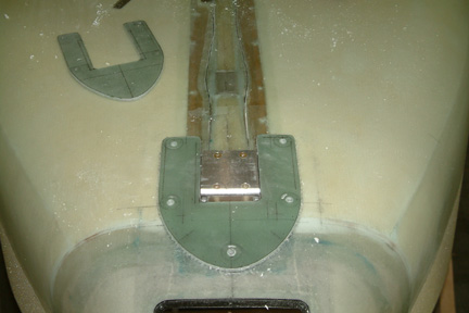 Once
the BID layers cured, I traced the bumper base pattern onto the top of the BID with the same
paper template. Then I popped it off the fuselage and trimmed it to shape with a
band saw and various sanding sticks. Note I have a smaller one close
by... that was one of those measured ONCE and end up cutting too short kind of part
Once
the BID layers cured, I traced the bumper base pattern onto the top of the BID with the same
paper template. Then I popped it off the fuselage and trimmed it to shape with a
band saw and various sanding sticks. Note I have a smaller one close
by... that was one of those measured ONCE and end up cutting too short kind of part
 I
also built up (5) 16 ply BID anchors on the opposite side of the bolt
holes (for the nose bumper base to bolt to). These L-shaped BID anchors are mounted
with its vertical leg against either F-0 or NG-30 as appropriate. The largest BID
tab is at the inside of the nose cone - right in front of F-0. If you look close,
you can see its silhouette in the above picture. With these 5 bolts and nuts,
the bumper base can be held tightly against the strengthened underside of the
fuselage and nose cone.
I
also built up (5) 16 ply BID anchors on the opposite side of the bolt
holes (for the nose bumper base to bolt to). These L-shaped BID anchors are mounted
with its vertical leg against either F-0 or NG-30 as appropriate. The largest BID
tab is at the inside of the nose cone - right in front of F-0. If you look close,
you can see its silhouette in the above picture. With these 5 bolts and nuts,
the bumper base can be held tightly against the strengthened underside of the
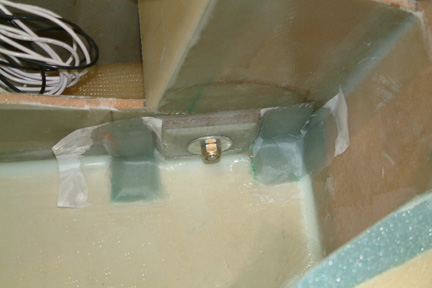
fuselage and nose cone.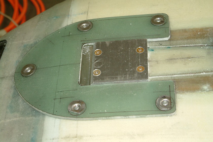 I
wanted the mounting bolts to stay flush with the fiber glass bumper base
because if the grinding ever gets down to the bolt heads, the bumper base will come off
in record time. I found some tee nuts from McMaster-Carr, but they only handle 1/4" 20
bolts only (I would prefer 10-32 threads). I had to shorten the tee nut necks to match the thickness
of the
bumper base. I also had
to open up the thru holes to accommodate its 5/16" neck diameter. Then I applied a bit of
flox to hold the tee nuts in the holes. With the bolts coming up from the inside of
the fuselage, I can pull the bumper base tightly against the fuselage bottom (as
shown). The surface of the BID is just about level with the 1/4" aluminum
strut plate.
I
wanted the mounting bolts to stay flush with the fiber glass bumper base
because if the grinding ever gets down to the bolt heads, the bumper base will come off
in record time. I found some tee nuts from McMaster-Carr, but they only handle 1/4" 20
bolts only (I would prefer 10-32 threads). I had to shorten the tee nut necks to match the thickness
of the
bumper base. I also had
to open up the thru holes to accommodate its 5/16" neck diameter. Then I applied a bit of
flox to hold the tee nuts in the holes. With the bolts coming up from the inside of
the fuselage, I can pull the bumper base tightly against the fuselage bottom (as
shown). The surface of the BID is just about level with the 1/4" aluminum
strut plate.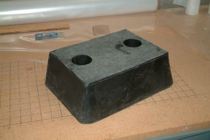 I
ordered a SBR loading dock bumper from McMaster Carr the next day and it arrived
promptly - this thing is monstrous
I
ordered a SBR loading dock bumper from McMaster Carr the next day and it arrived
promptly - this thing is monstrous 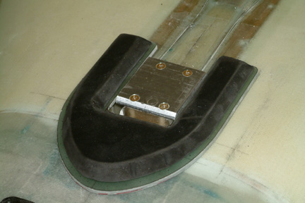 I
made another paper template for the tire materials - just a bit smaller than the
bumper base. I traced it out onto the rubber sheet and rough cut it out with my
band saw (4 TPI blade). Then I shaped the edges with my table belt sander and various
sanding sticks. This material was difficult to shape, as expected, but
eventually, the nose bumper took shape. I further cut out small pockets at the
underside of the bumper to accommodate the slight protrusions of the tee nuts.
I
made another paper template for the tire materials - just a bit smaller than the
bumper base. I traced it out onto the rubber sheet and rough cut it out with my
band saw (4 TPI blade). Then I shaped the edges with my table belt sander and various
sanding sticks. This material was difficult to shape, as expected, but
eventually, the nose bumper took shape. I further cut out small pockets at the
underside of the bumper to accommodate the slight protrusions of the tee nuts. 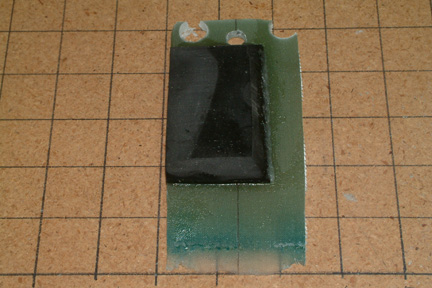 After
the flox cured, I clamped the the test sample at the base and took my belt
sander to it. This time I was looking for tear and separation of the rubber from
the fiber glass. They stay bonded quite well - I think it will take a lot of shear force
to separate the two. I do not know how much because I was not able to do
so... Note the little bit of flox along the edges probably helped as well. However, I was able to separate the two by prying them apart
(peeling). But I have to break through the flox first, that's why I'll be floxing
down the edges of the rubber and enclosing it with 2 ply BID. If you look
close, you can see part of the rubber at the top was removed by my belt sander.
After
the flox cured, I clamped the the test sample at the base and took my belt
sander to it. This time I was looking for tear and separation of the rubber from
the fiber glass. They stay bonded quite well - I think it will take a lot of shear force
to separate the two. I do not know how much because I was not able to do
so... Note the little bit of flox along the edges probably helped as well. However, I was able to separate the two by prying them apart
(peeling). But I have to break through the flox first, that's why I'll be floxing
down the edges of the rubber and enclosing it with 2 ply BID. If you look
close, you can see part of the rubber at the top was removed by my belt sander.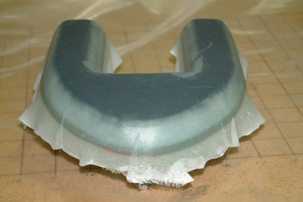 My
next step was to enclose the entire assembly with 2 plies BID. I first shape
the edges of the fiber glass to conform to the slope of the rubber bumper. Once
completed, I applied dry flox all around its edges, filling in any gaps and
irregularities. Right before I laid the 2 BID layers, I brushed over the dry
flox with epoxy, making it nice and smooth. The flox, in some way, encased the
rubber in place inside the 'shoe'. Then I laid on the 2 ply BID and peel
plied. Once it cured, I trimmed off the overhanging glass. Total weight of
the nose bumper is 14 oz. Since it is at the nose, maybe I can reduce some
ballast instead.
My
next step was to enclose the entire assembly with 2 plies BID. I first shape
the edges of the fiber glass to conform to the slope of the rubber bumper. Once
completed, I applied dry flox all around its edges, filling in any gaps and
irregularities. Right before I laid the 2 BID layers, I brushed over the dry
flox with epoxy, making it nice and smooth. The flox, in some way, encased the
rubber in place inside the 'shoe'. Then I laid on the 2 ply BID and peel
plied. Once it cured, I trimmed off the overhanging glass. Total weight of
the nose bumper is 14 oz. Since it is at the nose, maybe I can reduce some
ballast instead.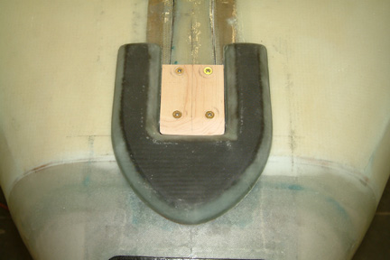 Here's
a picture of my completed nose bumper. Once it is painted to the same color of
the plane, it should be less 'visible'. I also made a nose strut skid
plate out of maple wood. I was surprised how hard the wood is and its resistance
to sanding. It gets hot, but localized - nothing like a metal plate. Note I
extended the length of the maple wood strut plate so that it covers up the
hole forward of the plate - but you need to slope the front edge so that it
does not interfere with the bumper edge.
Here's
a picture of my completed nose bumper. Once it is painted to the same color of
the plane, it should be less 'visible'. I also made a nose strut skid
plate out of maple wood. I was surprised how hard the wood is and its resistance
to sanding. It gets hot, but localized - nothing like a metal plate. Note I
extended the length of the maple wood strut plate so that it covers up the
hole forward of the plate - but you need to slope the front edge so that it
does not interfere with the bumper edge.