The instrument panel cover (IP cover) is a separate component that bridges between the forward deck and the IP. I always wondered why the IP cover and the forward deck were designed as two separate components. In addition, one has to contend with mounting mechanisms for both as well as a seal at their joining seam - a leakage source right above the electronic instruments. I later learned that the forward deck of the Cozy III is not removable - but was re-designed as removable for the Cozy IV - resulting in two separate removable parts. I took some time and looked up the archives and sought opinions from various builders and flyers. A few builders had thought about it, but I was surprised that I was not able to find any builder who actually combined the two pieces into one.
Since
my forward deck is held by three hinges and removing it was quite simple, I felt
that there was a lot of convenience piggy-backing the IP to the forward deck.
Besides, joining the two components into one eliminates the seam between the two
- thus eliminating any chance for water leakage onto the electronic
instruments below. So, against well meant advice, I decided to make an attempt
to join the IP cover to the forward deck - that will not be per plan. I hope I made the right
decision and an 'I told you so' will be humbly accepted![]() ...
...
Carving the Foam Mold
With the forward deck in place, I projected the drip rail curvature (which equates to my canopy curvature) towards the IP. Using two (2) paper templates (top and bottom), I pre-marked a 2" urethane foam and started carving until I got a uniform shape. |
Shaping Foam for the IP Hood
I rounded the edge along a 1/4" thick foam with my router and cut them into 1" wide strips. Then I 5-minute epoxied them along the top profile of the IP. This foam strip will help to form a nice round edge at the aft end of the IP cover. |
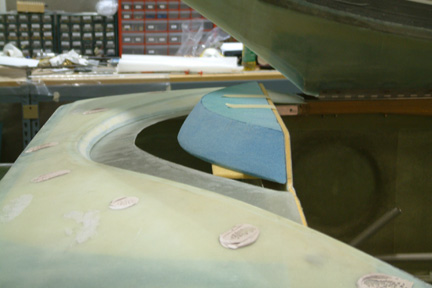
Unexpected Interference
|
|
|
Preparing the Foam Mold for Glassing
|
Glassing the IP cover
|
|
|
|
Once glassed, I peel plied the entire mold especially the joining seam. Note the peel ply went past the joining seam about 1" forward. Allowed to cure overnight... |
|
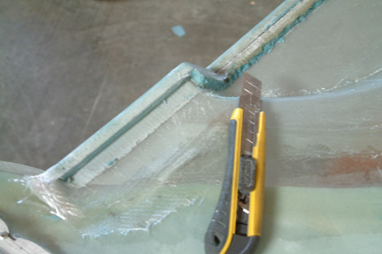
I flipped the IP cover over and started to work on the underside of the overhanging hood. I drew a nice straight cut-line at the under side of the rounded edge. Using my FEIN tool, I made a straight cut on the cured BID of the cut-line. Then I followed up with my blade through the foam. Notice the duct tape underneath? That was difficult to remove. Eventually, I had to dig out more foam to get all the duct tape out. |
|
I made a flox corner and glassed it with 2 plies of BID. I also added two plies along the under side of the seam and the entire drip rail - just to add more stiffness to the entire structure. |
|
This is how the IP cover / forward deck combination turned out...No seam and no joints in between to make. |
|
|
Angle Brackets
* I decided not to drill the hole and mount the nut plates until I am ready to mount the instruments such that I know, for sure, where the screws should be...
Since my effort is not quite to plan, I have taken a lot of pictures on this section. Send me an email and I shall get them to you. |
 Recall
that I extended the drip rail for the forward deck all the way to the canopy lip
profile (Section 15). Actually, I was already contemplating joining the IP cover
to the forward deck as one, I just couldn't visualize how to do it at the time...
Recall
that I extended the drip rail for the forward deck all the way to the canopy lip
profile (Section 15). Actually, I was already contemplating joining the IP cover
to the forward deck as one, I just couldn't visualize how to do it at the time...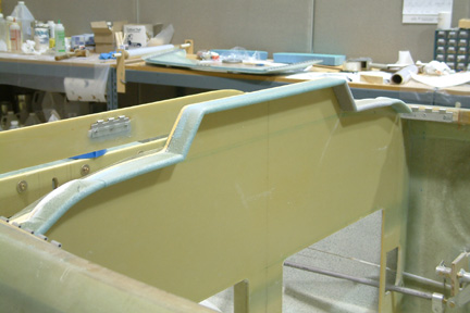 The
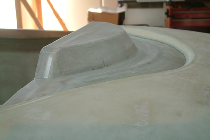
second part of the IP cover is the aft edge (i.e. the hood) over
the instrument panel. This entire part is the first thing you see as you open up
the canopy. Do a poor job here and you won't have to worry about anybody asking
for a ride
The
second part of the IP cover is the aft edge (i.e. the hood) over
the instrument panel. This entire part is the first thing you see as you open up
the canopy. Do a poor job here and you won't have to worry about anybody asking
for a ride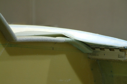 With
the IP hood completed, I mounted the forward deck back in place for a trial fit
and
With
the IP hood completed, I mounted the forward deck back in place for a trial fit
and 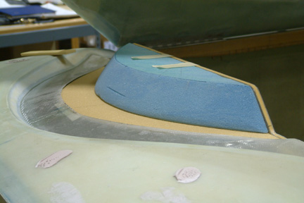 I added a flat piece of foam that bridges the top edge of the instrument panel sides
to the edge of my 'drip rail' (yellow foam). This is where I'll join the two (2) parts (i.e.
the forward deck and the IP cover). Since my drip rail hugs the canopy, the only
way I can attach glass to the drip rail is from the underside. So my 2-layer BID has to go from the top of the newly carved foam and then slip under
the drip rail at the seam...My concern is how well the seam is going to look? I
decided to press on...
I added a flat piece of foam that bridges the top edge of the instrument panel sides
to the edge of my 'drip rail' (yellow foam). This is where I'll join the two (2) parts (i.e.
the forward deck and the IP cover). Since my drip rail hugs the canopy, the only
way I can attach glass to the drip rail is from the underside. So my 2-layer BID has to go from the top of the newly carved foam and then slip under
the drip rail at the seam...My concern is how well the seam is going to look? I
decided to press on...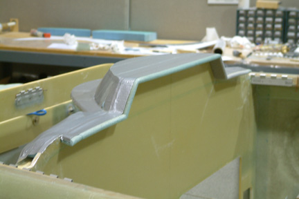 I
5-minute epoxied all foam blocks to the IP. Then I taped down the entire foam mold
with duct tape except the very aft edge of the IP cover (~1/4"). This is
part of my approach to give the IP cover a nice rounded feature per plan. It will
become clear as I get to that stage. I microed the exposed foam after I finished
applying the duct tape.
I
5-minute epoxied all foam blocks to the IP. Then I taped down the entire foam mold
with duct tape except the very aft edge of the IP cover (~1/4"). This is
part of my approach to give the IP cover a nice rounded feature per plan. It will
become clear as I get to that stage. I microed the exposed foam after I finished
applying the duct tape.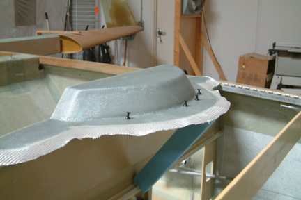 Glassing
the IP cover was not as difficult as anticipated. I removed the forward deck for
accessibility. I also used sticks of scrap foam to support the foam base such that
the forward edge butts against the aft edge of the drip rail. Note the stick of
scrap foam (blue) under the foam base and the over hang glass? I used a few more
scrap foam sticks to ensure a nice joint between the mating EDGES later on. I wetted out
the overhang glass with a brush and credit card (for holding up the glass). The over hang glass will
be attached to the underside of the drip rail.
Glassing
the IP cover was not as difficult as anticipated. I removed the forward deck for
accessibility. I also used sticks of scrap foam to support the foam base such that
the forward edge butts against the aft edge of the drip rail. Note the stick of
scrap foam (blue) under the foam base and the over hang glass? I used a few more
scrap foam sticks to ensure a nice joint between the mating EDGES later on. I wetted out
the overhang glass with a brush and credit card (for holding up the glass). The over hang glass will
be attached to the underside of the drip rail. 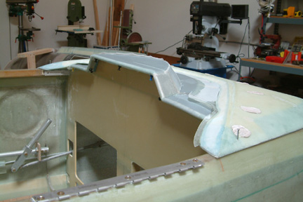 Then I re-mounted the forward deck
back in place.
I have to reach under the forward deck to brush the
overhang glass onto the underside of the drip rail. I also wrapped the glass over
the rounded edge of the IP hood. If you look close, you can see the stick pins
(at the underside of the IP hood) I used to hold the glass in
place.
Then I re-mounted the forward deck
back in place.
I have to reach under the forward deck to brush the
overhang glass onto the underside of the drip rail. I also wrapped the glass over
the rounded edge of the IP hood. If you look close, you can see the stick pins
(at the underside of the IP hood) I used to hold the glass in
place. 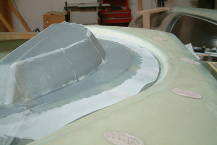
 Once
cured, I removed all the peel ply and popped the forward deck/IP cover
combination off the foam mold. Actually, it did not pop off at all, I had to
cut and pry, cut and pry, cut and pry some more to get the darn mold
off...Obviously, the foam mold was totaled...
Once
cured, I removed all the peel ply and popped the forward deck/IP cover
combination off the foam mold. Actually, it did not pop off at all, I had to
cut and pry, cut and pry, cut and pry some more to get the darn mold
off...Obviously, the foam mold was totaled...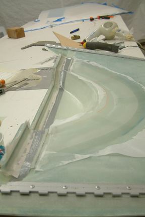
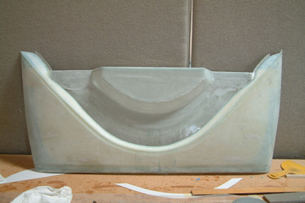 Here's
another view of the IP cover. Initially, I was a bit concerned that the entire
assembly may be somewhat big to handle, it turned out to be quite easy to
manage. With the three (3) hinge rods, the entire cover comes off with no
problem.
Here's
another view of the IP cover. Initially, I was a bit concerned that the entire
assembly may be somewhat big to handle, it turned out to be quite easy to
manage. With the three (3) hinge rods, the entire cover comes off with no
problem. 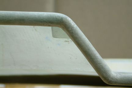 I
didn't care for the two metal angle brackets to be mounted at the aft face of
the IP - looks odd to me. Besides, it will take up valuable
frontal space. I decided to hide it a bit by adding two fiberglass tabs that are
attached to the IP cover and butt against the forward side of the instrument
panel. I will mount an 8-32 nut plate on each tab. The screws will go through the
IP and bolt to the nut plate.
I
didn't care for the two metal angle brackets to be mounted at the aft face of
the IP - looks odd to me. Besides, it will take up valuable
frontal space. I decided to hide it a bit by adding two fiberglass tabs that are
attached to the IP cover and butt against the forward side of the instrument
panel. I will mount an 8-32 nut plate on each tab. The screws will go through the
IP and bolt to the nut plate.