Establishing the BLs
 The
two main ribs for the strake are R33 and R57. To make sure I got them parallel
to the center line of the fuselage, I did the following:
The
two main ribs for the strake are R33 and R57. To make sure I got them parallel
to the center line of the fuselage, I did the following:
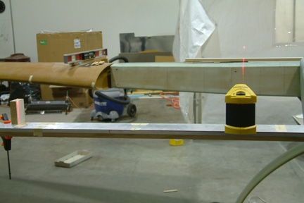
- Confirmed the centerline of the fuselage (nose tip to firewall) using my laser line;
- Clamped a long straight edge against the Instrument Panel and extended it out to the side of the fuselage (shown left where the laser is sitting on);
- Hot-glued another straight edge against the firewall, extending out perpendicular to the center line of the fuselage;
- Marked BL22, then every 10" outwards, all the way to BL60 on both straight edges;
- Used my laser to line up each pair of BL from front to back while casting a vertical line onto the forward face of the center section spar;
- Add BL33 and BL57 onto the center section spar.
Notice the laser line on the small white block to the side? It's for making sure the laser is square from side to side and front to back.
The WL17.4 was not too hard to mark, between the laser and digital levels, I have it marked from the wing root, along the center section spar and the entire fuselage side. I found my WL to my right wing is almost right on (may be 1/32" off), while the WL to my left wing is ~1/16" off. I figure its good enough for me...
 I
did not build the table per plan right away because I wanted to be able to get
to the under side of the top skin when building the 'T-hats' and the table
top would be in the way. In addition, with the Feather Lite leading edge, I need
to squeeze (clamp) the leading edge surfaces onto the top and underside of the ribs,
access space will be much needed. Instead, I used a couple of clamping work
benches and straight boards to hold the 2 ribs in place for glassing.
I
did not build the table per plan right away because I wanted to be able to get
to the under side of the top skin when building the 'T-hats' and the table
top would be in the way. In addition, with the Feather Lite leading edge, I need
to squeeze (clamp) the leading edge surfaces onto the top and underside of the ribs,
access space will be much needed. Instead, I used a couple of clamping work
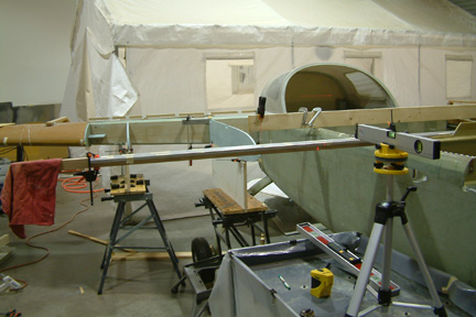
benches and straight boards to hold the 2 ribs in place for glassing. 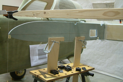 To
establish the forward tip location of the ribs, I used
a 1"x3" beam and a plumb line. I placed a masking tape on the plumb
line string (5.6" below the bottom of the beam) - that's the WL17.4. Then I
placed the plumb line in-line with the laser beam. That establishes where the tip
of the rib should go. All I need to do is to line up the tip of the ribs to the
plumb line, with its WL17.4 marking to the same height as the masking tape. I
glassed the ribs onto the center section spar with 2 layers of BID on each
corner.
To
establish the forward tip location of the ribs, I used
a 1"x3" beam and a plumb line. I placed a masking tape on the plumb
line string (5.6" below the bottom of the beam) - that's the WL17.4. Then I
placed the plumb line in-line with the laser beam. That establishes where the tip
of the rib should go. All I need to do is to line up the tip of the ribs to the
plumb line, with its WL17.4 marking to the same height as the masking tape. I
glassed the ribs onto the center section spar with 2 layers of BID on each
corner.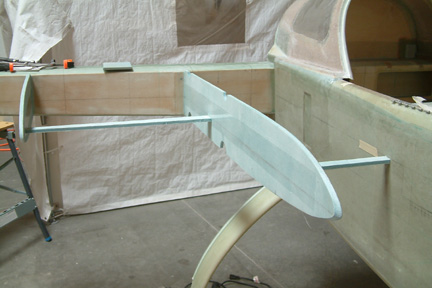 Since
I did not have a table top to support the ribs (after they are glassed in), they
tend to flop sideways a bit when bumped. To stabilize them for fitting the
Feather Lite LE, I added a couple of temporary stringers which helped quite a
bit. They will be removed after the LE is installed.
Since
I did not have a table top to support the ribs (after they are glassed in), they
tend to flop sideways a bit when bumped. To stabilize them for fitting the
Feather Lite LE, I added a couple of temporary stringers which helped quite a
bit. They will be removed after the LE is installed.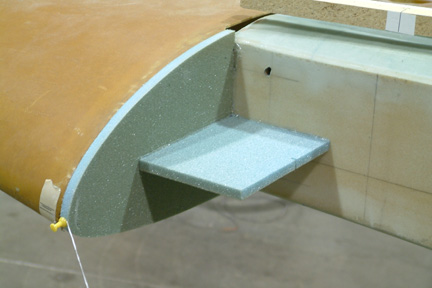 Since
I will be using the Feather Lite leading edge, I will need some kind of a
template to clamp my leading edge to. I decided to add an end rib, with the same
curvature profile as the wing root for this requirement.
Since
I will be using the Feather Lite leading edge, I will need some kind of a
template to clamp my leading edge to. I decided to add an end rib, with the same
curvature profile as the wing root for this requirement.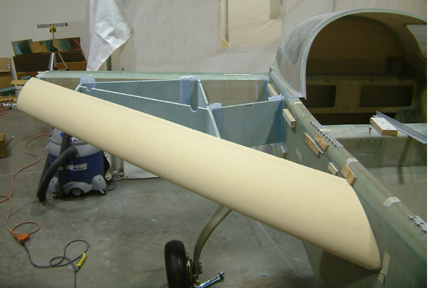 Since
holding the bulkheads in place for glassing without the table and bottom skin is
a kind of a challenge - here's what I did...
Since
holding the bulkheads in place for glassing without the table and bottom skin is
a kind of a challenge - here's what I did...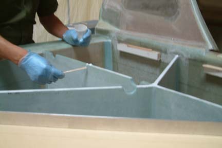 I
wet out 2-ply 2" BID strips (the top strip of the T-Hat) with peel-ply on
one side. I centered the BID tape at the pencil mark with the peel-ply side to
the packing tape. I then applied a thin layer of wet micro on top of the ribs and
bulkheads. With Susann's help, we laid the top back onto the strake and weighted
it down to cure.
I
wet out 2-ply 2" BID strips (the top strip of the T-Hat) with peel-ply on
one side. I centered the BID tape at the pencil mark with the peel-ply side to
the packing tape. I then applied a thin layer of wet micro on top of the ribs and
bulkheads. With Susann's help, we laid the top back onto the strake and weighted
it down to cure.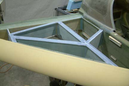
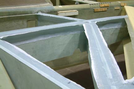 But
I have to do something to make it look crappy again...I made a bunch of wet flox
and 'whipped' it really good during mixing. The reason for whipping it is to get
rid of the lumps normally formed with the cotton. Since we wanted to get a good
seal, whipped cotton is less lumpy. I floxed all edges and corners, then I
added the 2" 'T' glass strip joining the top sides of the ribs/bulkheads to
the underside of the top strip. Actually there were many strips. By the time I
came back to do the peel- ply, the glass was already curing...
But
I have to do something to make it look crappy again...I made a bunch of wet flox
and 'whipped' it really good during mixing. The reason for whipping it is to get
rid of the lumps normally formed with the cotton. Since we wanted to get a good
seal, whipped cotton is less lumpy. I floxed all edges and corners, then I
added the 2" 'T' glass strip joining the top sides of the ribs/bulkheads to
the underside of the top strip. Actually there were many strips. By the time I
came back to do the peel- ply, the glass was already curing...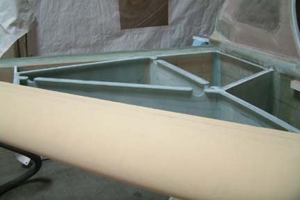
 I
did not cut out the fuel drain viewing window until now because I wanted to make
sure I can see the fuel drain location. As many Cozy builders before, I moved
the sight window an extra 3" forward per plans dimension. Actually, I wished I moved it up 1" higher
as well - a bit late for me though. Regardless, I can see the fuel drain from
the fuel filler cap location fine. Note the small target I placed on top of the
white board? That represents my fuel drain location. The only problem with this
approach is the limited space you'll have to cut the fuel drain window this late
in the game.
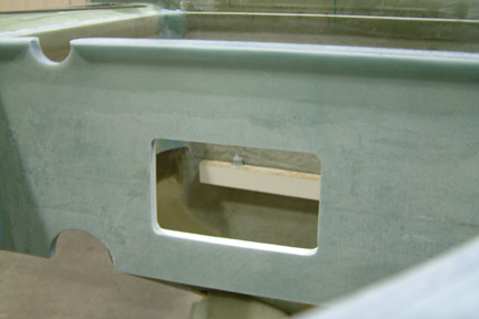
I
did not cut out the fuel drain viewing window until now because I wanted to make
sure I can see the fuel drain location. As many Cozy builders before, I moved
the sight window an extra 3" forward per plans dimension. Actually, I wished I moved it up 1" higher
as well - a bit late for me though. Regardless, I can see the fuel drain from
the fuel filler cap location fine. Note the small target I placed on top of the
white board? That represents my fuel drain location. The only problem with this
approach is the limited space you'll have to cut the fuel drain window this late
in the game. 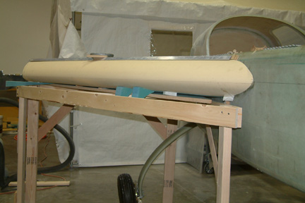 Whatever
it is, I just had a real difficult time in building a sturdy table to support
the bottom skin. To make things more complicated, the Feather Lite LE takes its
own form and just does not fit well with the table. By the time I fit the table
in place, I lost all visibility on the bottom skin - just won't know how the
bottom skin fits until its all cured and done - or worse, after it is too late.
Whatever
it is, I just had a real difficult time in building a sturdy table to support
the bottom skin. To make things more complicated, the Feather Lite LE takes its
own form and just does not fit well with the table. By the time I fit the table
in place, I lost all visibility on the bottom skin - just won't know how the
bottom skin fits until its all cured and done - or worse, after it is too late.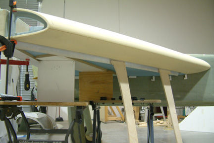 I
decided to abandon the table and try other simpler supporting methods. Again, I
turned back to my angle aluminum beam, C-clamps and clamping work benches. Here's
a picture of my alternative approach. I did measure the slope of the bottom skin
sideways (same as the center section spar) and forward and backwards as the
fuselage. This way, I can inspect and feel the bottom skin when it is in place
for floxing. I can check for any sagging, the straightness of the seams between
the LE and bottom skin and the trailing edge of the bottom skin. This set up just
looks simpler to me - will see how it turns out.
I
decided to abandon the table and try other simpler supporting methods. Again, I
turned back to my angle aluminum beam, C-clamps and clamping work benches. Here's
a picture of my alternative approach. I did measure the slope of the bottom skin
sideways (same as the center section spar) and forward and backwards as the
fuselage. This way, I can inspect and feel the bottom skin when it is in place
for floxing. I can check for any sagging, the straightness of the seams between
the LE and bottom skin and the trailing edge of the bottom skin. This set up just
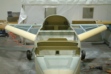
looks simpler to me - will see how it turns out.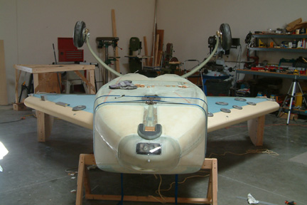 Here's
a picture of my bottom skins after I flip the fuselage over with the
clamshells. This approach allows me to see the bottom skin surface and
profile nicely before floxing it in place.
Here's
a picture of my bottom skins after I flip the fuselage over with the
clamshells. This approach allows me to see the bottom skin surface and
profile nicely before floxing it in place.