Chapter
21 - Section 7
Bottom
Outside Skin and Sump
Turn
Fuselage Over / Clamshell
I
jumped ahead to make the clamshell so that I can turn the fuselage over
earlier in my building process. I delayed putting the bottom skin on per plan
because I need the access space from the bottom to install the Feather Lite
leading edge. Now that the LE, ribs and bulkheads, vent lines and tank coating
are in place, I can proceed to install the top and bottom skins. Since I am not
too keen on the support table (per plan), I decided to turn the fuselage over to
micro the bottom skin in place - IF I can turn the fuselage over easily.
I
have seen many methods that were used to turn the fuselage over. Some builders used the
neighborhood army while others devised a large clamshell rollover structure. The
smallest clamshell, I observed, was from Jon Dembs's web site. I decided to
follow his idea...
|
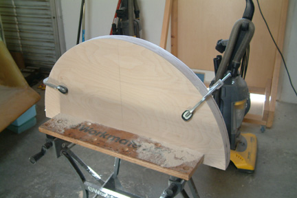 It
basically consists of 4 half circle boards and 4 2x4s. I happen to have enough
boards to make the two 30" diameter circles. I stacked the 4 half circles
together such that I can sand them down nicely. A uniform circumference should
allow the clamshell to roll smoothly. It
basically consists of 4 half circle boards and 4 2x4s. I happen to have enough
boards to make the two 30" diameter circles. I stacked the 4 half circles
together such that I can sand them down nicely. A uniform circumference should
allow the clamshell to roll smoothly.
|
|
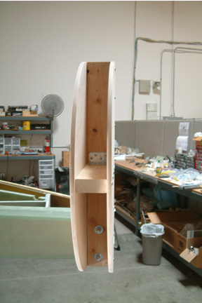 As
you can see I sandwiched two 2x4s (in the form of a T) between the half circles,
forming the clamshell roll over structure. I drilled two 1/2" holes through
then lower end of the 2x4 so that I could mount it onto the center section spar / wing bolt
holes (picture left). As
you can see I sandwiched two 2x4s (in the form of a T) between the half circles,
forming the clamshell roll over structure. I drilled two 1/2" holes through
then lower end of the 2x4 so that I could mount it onto the center section spar / wing bolt
holes (picture left).
These
clamshells took me 2 evenings to complete.
|
|
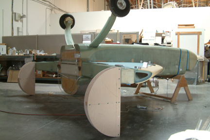
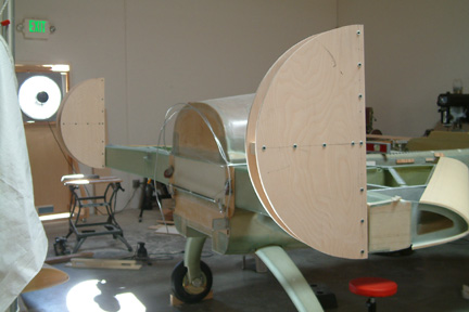 Here
a side view of both clamshells mounted onto the center section spar. Before
I attempted to flip the fuselage over, I removed all the hardware at the nose -
to reduce the initial lifting weight, or worse, the landing weight of the 'space
shuttle' as it descended on its back.
They include the rudder pedals, the electric nose lift and the electric elevator
control. Here
a side view of both clamshells mounted onto the center section spar. Before
I attempted to flip the fuselage over, I removed all the hardware at the nose -
to reduce the initial lifting weight, or worse, the landing weight of the 'space
shuttle' as it descended on its back.
They include the rudder pedals, the electric nose lift and the electric elevator
control.
|
|
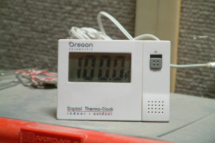 Notice my
modified whole house fan was going full throttle (above picture)... its one of
those Los Angeles blazing summer days as noted by my digital thermometer! The saw dust just loves to stick onto your skin like used gum Notice my
modified whole house fan was going full throttle (above picture)... its one of
those Los Angeles blazing summer days as noted by my digital thermometer! The saw dust just loves to stick onto your skin like used gum ... ...
We
call it Cozy commitment, don't we?
|
|
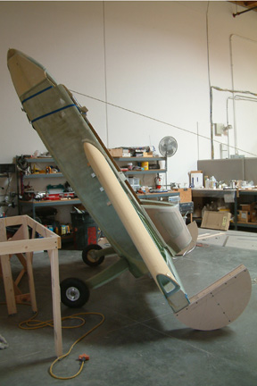 With
a bit of my neighbor's help, we flipped the fuselage over...it was not too
difficult. I don't think I could do it myself because the shape of my clamshell was a perfect half circle and with that geometry, I needed an extra lift to
'transition' from the main wheels onto the clamshells. I have to either trim the
bottom half of the clamshell a bit or get a taller person to give it the right
push when the fuselage is at its upright position. With
a bit of my neighbor's help, we flipped the fuselage over...it was not too
difficult. I don't think I could do it myself because the shape of my clamshell was a perfect half circle and with that geometry, I needed an extra lift to
'transition' from the main wheels onto the clamshells. I have to either trim the
bottom half of the clamshell a bit or get a taller person to give it the right
push when the fuselage is at its upright position.
|
|
 The
good news is that the clamshells held up very well, no wobbling or signs of
collapsing... The
good news is that the clamshells held up very well, no wobbling or signs of
collapsing... . .
Now I can
proceed with the bottom skin (Section 3).
|
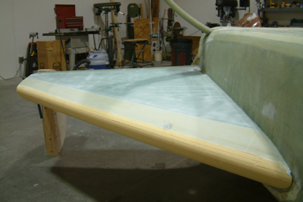
Preparing
Bottom Skin for Glassing
 I
smoothed out the bottom skin with a long sanding board making sure that there
are no bumps at the joining edges (leading edge and the rest of the top skin). I
also sanded down a 1" wide 1/32" deep trench parallel to the leading
edge per plan. I
smoothed out the bottom skin with a long sanding board making sure that there
are no bumps at the joining edges (leading edge and the rest of the top skin). I
also sanded down a 1" wide 1/32" deep trench parallel to the leading
edge per plan.
I
did not sand the bottom skin flush with the center section spar. Instead, I
smoothed out the height difference at the trailing edge of the bottom skin to the
center section spar with flox.
|
|
 To
ease trimming the UNI, I decided to make a paper template to guide me along.
Once completed, I taped down the paper template on my work table and laid out
the UNI on top of it for trimming. To
ease trimming the UNI, I decided to make a paper template to guide me along.
Once completed, I taped down the paper template on my work table and laid out
the UNI on top of it for trimming.
This
approach made the trimming of the UNI easier. However, it distracted my focus
and ended up with a BIG lay up error (discussed below)!
|
Oops...UNI Orientation
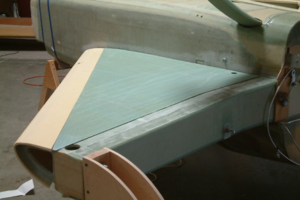
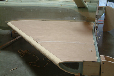
I cut
the UNIs (3 layers) with the template for the left wing first. Then I epoxied and peel plied them in place. The UNI fits onto the bottom skin nicely with
minimum pulling and tugging. No wrinkles or bubbles...I was happy how it all turned out.
The
next day, I used the right wing template and repeated the glassing and peel ply
process. Half way down the process, I kinda felt that the lay up I was doing,
was not quite the same as yesterdays' - though they should be the same . I just got that odd feeling that the shape of the UNI pieces
are not the same shape - of course not, I thought to myself, its the left and
right wing! But the lay up schedule are the
same for both wings, I argued. After completing the second wing, I can't wait to
check on the first. ~!@#$, I had the first layer of UNI in the wrong
orientation. Instead of parallel to the leading edge, I had it perpendicular to
the leading edge
. I just got that odd feeling that the shape of the UNI pieces
are not the same shape - of course not, I thought to myself, its the left and
right wing! But the lay up schedule are the
same for both wings, I argued. After completing the second wing, I can't wait to
check on the first. ~!@#$, I had the first layer of UNI in the wrong
orientation. Instead of parallel to the leading edge, I had it perpendicular to
the leading edge .
.
|
 After
chewing myself out for 5 minutes and receiving prompt advice from Wayne Hicks,
I added the third layer of UNI per plan. Now I have the strongest left
strake among the Cozy builders! After
chewing myself out for 5 minutes and receiving prompt advice from Wayne Hicks,
I added the third layer of UNI per plan. Now I have the strongest left
strake among the Cozy builders!
|
The
Exception Layer
Per
Plan, the 3rd layer is a 5" strip along the OD bulkhead. Since I
do not have the OD bulkhead, but an end rib. I added a 3rd layer
bridging my end rib with rib (R57) with UNI running perpendicular to the
fueslage.
Clear
Fuel Drain Valve
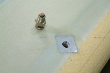 Once
the glass layers cured, I removed the UNI layers that covered up the fuel drain
valve hole with drill, Dremel tool, small files and sand paper. I re-tapped the
hard point slightly to clear any epoxy that might have gotten into the threads.
The effort was not substantial. Once
the glass layers cured, I removed the UNI layers that covered up the fuel drain
valve hole with drill, Dremel tool, small files and sand paper. I re-tapped the
hard point slightly to clear any epoxy that might have gotten into the threads.
The effort was not substantial.
Notice
the 1/32" indentation along the leading edge to accommodate the overlap between the
top and bottom layers?
|
Fuel
Sump
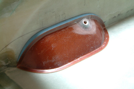 I
bought my fuel sump from FeatherLite together with my Leading Edge.
Unfortunately, the sump does not fit my fuselage perfectly. I have to add a
sliver of foam to fill the gap - note the blue foam strip. This foam strip
was used for building up a new, extended lip to match up to the fuselage sides. I
bought my fuel sump from FeatherLite together with my Leading Edge.
Unfortunately, the sump does not fit my fuselage perfectly. I have to add a
sliver of foam to fill the gap - note the blue foam strip. This foam strip
was used for building up a new, extended lip to match up to the fuselage sides.
|
|
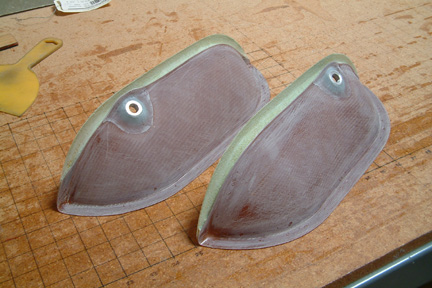 Here's
a picture of the new extended lip and the foam strip removed. Here's
a picture of the new extended lip and the foam strip removed.
|
|
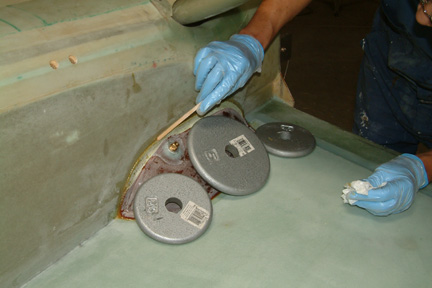 I
painted extra coats of E-Z Poxy onto the inside surfaces of the sump. Then lined
the sump lip with a thick layer of flox (using E-Z Poxy) and weighed it down against
the fuselage and bottom skin of the wing. Then I smoothed out the squeezed out
flox to assure a good seal. I
painted extra coats of E-Z Poxy onto the inside surfaces of the sump. Then lined
the sump lip with a thick layer of flox (using E-Z Poxy) and weighed it down against
the fuselage and bottom skin of the wing. Then I smoothed out the squeezed out
flox to assure a good seal.
|
|
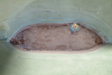 Final
floxing and glassing of sump in place. Final
floxing and glassing of sump in place.
|
Water
Test (Addition to Plan)
I
heard many horror stories about the upcoming leak test, I decided to take a
small 'informal' leak test before the big day... At this point of my build, I
already have the bottom skin glassed, outlet piping floxed in, fuel sump glassed
in, fuel drains installed, and inner tank coated with 3 layers of E-Z Poxy. I
decided to add a bit of water in the tank to see if any leak occurs. Both sumps
took almost the same amount of water ~30 oz each. The fuel drain in the sump,
outlet piping and the sump are totally submerged. Then I lower the nose a bit
and added more water onto the fuel tank (my top is not installed yet) such that
the water level covers up the fuel drain at the leading edge. I was pleased
to see that the water pattern on both sides of the tank were quite symmetrical.
I let them sat overnight.
I
returned the next morning and found a couple of drips at the temporary
termination plug at the fuel line inside the fuselage (right). I realized I only
hand tightened them when I installed them. I re-tightened them with a wrench and
wiped dry. Then I allowed them to sit overnight again.
All
was well the next day - no leak! I was surprised at the amount of fine dust/debris
which floated on the top of the water surface. I used my ShopVac with a small
suction tube and skimmed off the debris on the top surface. Then I opened up the fuel
drain plugs and drained all the water out. I was surprised at the weight of all
the water I added to the tanks for this mini test.