Chapter
22 - Section 1
Basic System w/Alternator
Introduction
My knowledge with an aircraft electrical system is very
limited. I started reading Bob Nuckolls book while I was in the filling and
sanding phase. Between the hard labor and technical reading - a good night's sleep
was guaranteed. Between reading all the postings on instrument panels and wiring
approaches, I was getting information overload. The bottom line was, I really do
not know what I should have for my IP, let alone how to get there!
Tim Andres came to the rescue. He flew down from Red
Bluff and stayed with me for several days. During that time, he gave me a
valuable education on basic aircraft electrical wiring techniques, safety
specifications, instrument/component selections as well as reliable sources to
purchase them. Thank you Tim - for a clear path to march forward. My first
milestone was to start with the backbone wiring. That included the power
distribution system and wiring such that I can turn on the basic electrical components (actuators, etc.) that are already installed in the plane structure.
EZ Points, Click Bonds & Perforated Base Studs
As I entered this chapter, I started hearing terms like
click bonds and EZ points, being used for securing electrical components,
devices and wire hooks etc. (I assume you know what they look like). I was surprised how
expensive they are. Generally, they cost $3 to $4 each at Aircraft Spruce and
other retail stores. You can get a much better price from the Cozy Girrrls and
JD Newman for around 50 to 70 cents each. Personally, I just do not understand
why they are so expensive? Expecting to use a lot of them throughout the wiring
process, I started to look around for a better price with no luck. Some users
even took the time to drill a bunch of small holes at the base of the click
bonds to enhance their floxing characteristics.
 As the basic electrical wiring, components, tools were
arriving, I started to lay them out on a mock up firewall. It did not take long
for me to realize I am going to be running out of room. They included the
battery, the master contactor, starter contactor, all the external regulator controls for
both of my alternators (L60 and SD8), Princeton fuel probe controls, terminal blocks (switched
& un-switched), ground terminal block, the electronic ignition control box, engine
monitor unit and the manifold pressure monitor box. I have to blame the cluttering culprit to the external regulators
for both of my alternators. If I were to do it over again, I would have bought the
internal regulated alternators. Four of the 11 components that mount onto the
internal firewall belong to the two regulators!
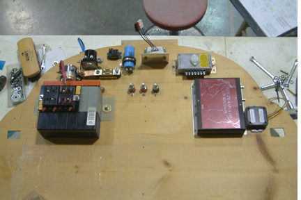
As the basic electrical wiring, components, tools were
arriving, I started to lay them out on a mock up firewall. It did not take long
for me to realize I am going to be running out of room. They included the
battery, the master contactor, starter contactor, all the external regulator controls for
both of my alternators (L60 and SD8), Princeton fuel probe controls, terminal blocks (switched
& un-switched), ground terminal block, the electronic ignition control box, engine
monitor unit and the manifold pressure monitor box. I have to blame the cluttering culprit to the external regulators
for both of my alternators. If I were to do it over again, I would have bought the
internal regulated alternators. Four of the 11 components that mount onto the
internal firewall belong to the two regulators!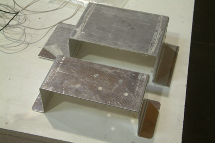 I started planning my electrical system from the battery.
I bought the same battery most Cozy builders use (PC680)
as my starting point. In order to keep the battery securely in place, I must
first fabricate a strap of some sort to hold it in place. I started with 0.050"
thick 2024 T3 aluminum sheet and cut out a 4" strip. Then I made 4 90 degree
bends to it. I feel I must make it really snug such that there is absolutely no
movement between the battery and the strap. I'll be the first to admit that I
am just not a good sheet metal bender... I forgot to add the thickness of the
metal sheet. As a result, my strap was too loose. Trial #2 turned out to be too
tight...
I started planning my electrical system from the battery.
I bought the same battery most Cozy builders use (PC680)
as my starting point. In order to keep the battery securely in place, I must
first fabricate a strap of some sort to hold it in place. I started with 0.050"
thick 2024 T3 aluminum sheet and cut out a 4" strip. Then I made 4 90 degree
bends to it. I feel I must make it really snug such that there is absolutely no
movement between the battery and the strap. I'll be the first to admit that I
am just not a good sheet metal bender... I forgot to add the thickness of the
metal sheet. As a result, my strap was too loose. Trial #2 turned out to be too
tight...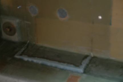 Building
the raised step for the battery was a bit more complicated than expected. First
I put packing tape over the lower 2" of the battery. Then I strapped and shimmed
the battery against the firewall (after the BID cures). Then I formed a flox
perimeter (or filled the gap) under the battery with wet flox. After the flox
cured, I removed the battery.
Building
the raised step for the battery was a bit more complicated than expected. First
I put packing tape over the lower 2" of the battery. Then I strapped and shimmed
the battery against the firewall (after the BID cures). Then I formed a flox
perimeter (or filled the gap) under the battery with wet flox. After the flox
cured, I removed the battery.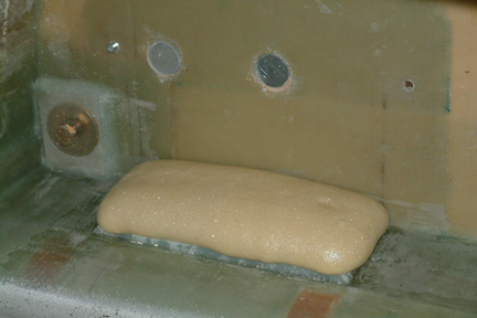 Add
some pour foam inside the flox cavity and shape it to a flat step. I got a bit
carried away with the pour foam here...Actually, I forgot how much pour foam
tends to grow.
Add
some pour foam inside the flox cavity and shape it to a flat step. I got a bit
carried away with the pour foam here...Actually, I forgot how much pour foam
tends to grow.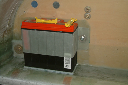 Here's
a picture when the battery is finally strapped in place!
Here's
a picture when the battery is finally strapped in place!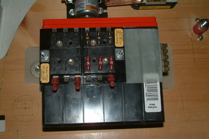 One
of the key functions of a fuse block is to protect the wires from over-heating.
Therefore, they should be located close to the power source (battery) prior to
distributing the power onwards. I picked the idea from Tim Andres by mounting my
switched, un-switched and ground terminal blocks onto the battery strap. I did
so by glassing 4 flat-based studs (discussed later) onto the strap.
One
of the key functions of a fuse block is to protect the wires from over-heating.
Therefore, they should be located close to the power source (battery) prior to
distributing the power onwards. I picked the idea from Tim Andres by mounting my
switched, un-switched and ground terminal blocks onto the battery strap. I did
so by glassing 4 flat-based studs (discussed later) onto the strap.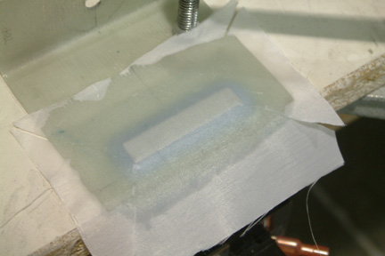 My
next step was to add the ground terminal to the battery strap as well. I bought
my ground terminal strip from SteinAir and it is somewhat flimsy. In order to
add more rigidity to the terminal block, I cut up a small strip of aluminum (1/8"
thick) that fits the foot print of terminal strip. Then I floxed and glassed the
aluminum onto the side of the strap (as shown).
My
next step was to add the ground terminal to the battery strap as well. I bought
my ground terminal strip from SteinAir and it is somewhat flimsy. In order to
add more rigidity to the terminal block, I cut up a small strip of aluminum (1/8"
thick) that fits the foot print of terminal strip. Then I floxed and glassed the
aluminum onto the side of the strap (as shown).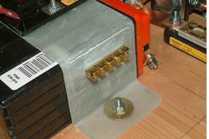 Once
cured, I drilled and tapped two 8-32 threaded holes into the embedded aluminum
hard point. Then I bolted the ground terminal to the hard point as shown.
Once
cured, I drilled and tapped two 8-32 threaded holes into the embedded aluminum
hard point. Then I bolted the ground terminal to the hard point as shown. 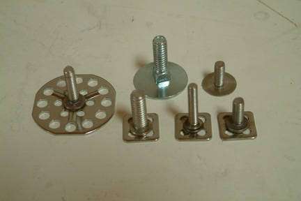 Finally
I stumbled into a discussion in VansAirForce forum that suggested an alternative
from McMaster Carr - a perforated base stud. I decided to look them up. To my
disappointment, they all have a large base (1 1/2" diameter) and cost from 70
cents to $1.30 each. While experimenting with it, I noticed the word 'Rotaloc'
stamped on the bottom side. Curiously enough, I looked them up on the Web. It
turned out they are the manufacturers of the part for McMaster and they come
with all types of base shapes and sizes. In addition, the studs also come with
different threads and lengths. They cost - 33 to 44 cents each. A quick
phone call got me several models and sizes in 3 days.
Finally
I stumbled into a discussion in VansAirForce forum that suggested an alternative
from McMaster Carr - a perforated base stud. I decided to look them up. To my
disappointment, they all have a large base (1 1/2" diameter) and cost from 70
cents to $1.30 each. While experimenting with it, I noticed the word 'Rotaloc'
stamped on the bottom side. Curiously enough, I looked them up on the Web. It
turned out they are the manufacturers of the part for McMaster and they come
with all types of base shapes and sizes. In addition, the studs also come with
different threads and lengths. They cost - 33 to 44 cents each. A quick
phone call got me several models and sizes in 3 days.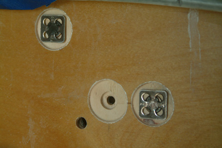 Here's
a picture of how I prepared them. I first drilled a 7/8" round step using a Forstner
bit. The step is just deep enough for the thickness of the perforated base. Then
I switched over to a 3/8" Forstner bit and drilled a second step to accommodate
the stud base. Then I followed with a drill bit through hole for the threaded stud
(as shown in the picture).
Here's
a picture of how I prepared them. I first drilled a 7/8" round step using a Forstner
bit. The step is just deep enough for the thickness of the perforated base. Then
I switched over to a 3/8" Forstner bit and drilled a second step to accommodate
the stud base. Then I followed with a drill bit through hole for the threaded stud
(as shown in the picture).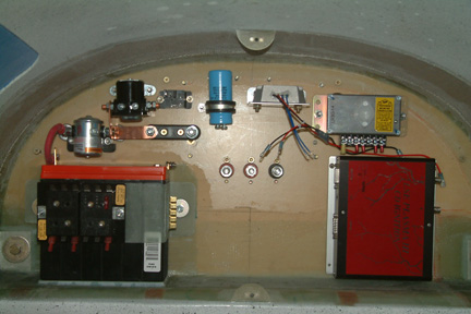 Here's
a picture of my fire wall using mostly the perforated base studs through the
fire wall. They include the battery, the master contactor, the starter
contactor, all the regulator components for my main (B&C L60) and backup
alternators (B&C SD-8), the ANL fuse block for the alternator and my electronic ignition controller. The three heavy
duty lugs in the middle are from Blue Sea System that carry the power to the
engine compartment - yet isolating the post from the firewall.
Here's
a picture of my fire wall using mostly the perforated base studs through the
fire wall. They include the battery, the master contactor, the starter
contactor, all the regulator components for my main (B&C L60) and backup
alternators (B&C SD-8), the ANL fuse block for the alternator and my electronic ignition controller. The three heavy
duty lugs in the middle are from Blue Sea System that carry the power to the
engine compartment - yet isolating the post from the firewall.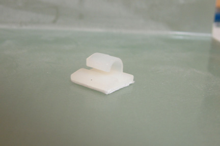 It
is good practice to route the wire in a manageable bundle such that they can be
traced, repaired or modified as needed. Since I am not experienced enough to
foresee how the wire routing will be, I decided to use stick on wire holders (on
a temporary basis) to guide my initial routing. I soon realized that these stick
on wire holders were difficult to remove, plus they leave a messy glue residue
on the fire wall.
It
is good practice to route the wire in a manageable bundle such that they can be
traced, repaired or modified as needed. Since I am not experienced enough to
foresee how the wire routing will be, I decided to use stick on wire holders (on
a temporary basis) to guide my initial routing. I soon realized that these stick
on wire holders were difficult to remove, plus they leave a messy glue residue
on the fire wall. 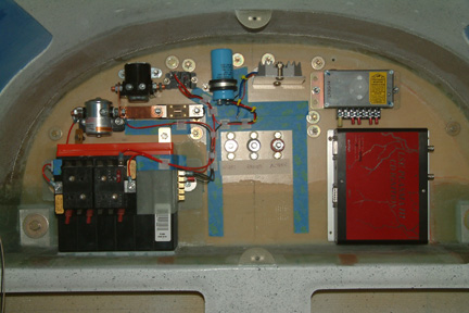 To
prevent this from recurring, I lay blue tape strips on the fire wall first to
block off the glue residue (as shown). That way, I can re-locate the wire
holders as I go along without any residue effect. Here's the preliminary wiring harness - starting to take
shape.
To
prevent this from recurring, I lay blue tape strips on the fire wall first to
block off the glue residue (as shown). That way, I can re-locate the wire
holders as I go along without any residue effect. Here's the preliminary wiring harness - starting to take
shape.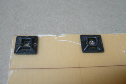 I finally settled on one of the most common cable ties (as shown
- Greenlite Cable Ties GMB-4A). It comes with
an adhesive back as well. However, I
removed the adhesive back (heat it up with a heat gun and the back peels right
off). Then I rough up the bottom of the cable tie mount and its mating surface
slightly with a 80 grit sand paper. Then I epoxy it in place. Initially, I used
my glassing epoxy. As wiring efforts proceeded slowly, I became impatient - I
just used 5 minute epoxy because it cured quickly. Surprisingly, these cable tie
mounts held their places very well. I have pulled and tug on them while
strapping the cables to it with my splice knots. Only two came off (out of ~100)
so far. With those, I put a small 4-40 counter sink screw through it for added
security. These mounts will not be coming off!
I finally settled on one of the most common cable ties (as shown
- Greenlite Cable Ties GMB-4A). It comes with
an adhesive back as well. However, I
removed the adhesive back (heat it up with a heat gun and the back peels right
off). Then I rough up the bottom of the cable tie mount and its mating surface
slightly with a 80 grit sand paper. Then I epoxy it in place. Initially, I used
my glassing epoxy. As wiring efforts proceeded slowly, I became impatient - I
just used 5 minute epoxy because it cured quickly. Surprisingly, these cable tie
mounts held their places very well. I have pulled and tug on them while
strapping the cables to it with my splice knots. Only two came off (out of ~100)
so far. With those, I put a small 4-40 counter sink screw through it for added
security. These mounts will not be coming off! 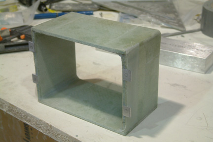 As more and more equipment arrived, I found there are
more and more components needed to be packed into the battery compartment. The latest are the engine and manifold pressure monitors. Since my GRT EFIS will be
reporting my engine status, there really is no need to place the engine monitor
controller on the IP. It makes more sense to mount it in the Battery
compartment (shorter wiring). In addition, the manifold pressure monitor (small black box)
receives information from the engine and reports it to the engine monitor. So, it
makes sense to placed the manifold pressure monitor in the battery compartment as well. I found the real
estate in the battery compartment is getting limited - quickly.
As more and more equipment arrived, I found there are
more and more components needed to be packed into the battery compartment. The latest are the engine and manifold pressure monitors. Since my GRT EFIS will be
reporting my engine status, there really is no need to place the engine monitor
controller on the IP. It makes more sense to mount it in the Battery
compartment (shorter wiring). In addition, the manifold pressure monitor (small black box)
receives information from the engine and reports it to the engine monitor. So, it
makes sense to placed the manifold pressure monitor in the battery compartment as well. I found the real
estate in the battery compartment is getting limited - quickly.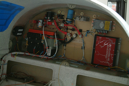 As
I moved forward to my wiring, the battery compartment started to get loaded.
Here's a updated picture of my battery compartment.
As
I moved forward to my wiring, the battery compartment started to get loaded.
Here's a updated picture of my battery compartment.