Picture #1
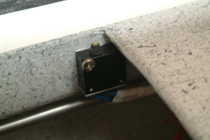
The first indicator light is for confirming the closure of
the canopy. I decided to mount the limit switch at the opening edge of my side
hinged canopy. I bought a couple water tight limit switches from Allelectronics
(Picture #1 black switch to the left) - they were inexpensive. To trigger the
limit switch, I made a small threaded plunger (aluminum), a threaded tubing
(~1/2" long) and a flat spacer (picture left). The tubing is floxed onto the
canopy and the plunger is screwed onto it. The reason for the threaded plunger
is to provide fine adjustment to the trigger height relative to the limit
switch. The spacer is to make sure the trigger button is centered to the
plunger.
Picture #2
The limit switch is then mounted directly to the longeron
with a couple screws. I position the switch a bit below the top of the longeron
to duck below any potential bumping during loading and unloading. Note the thin
space behind the limit switch?
Picture #3
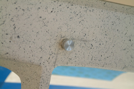
The threaded tubing is floxed into the pre-drilled hole on
the canopy such that it is flushed to the surface. Once the floxed cured, the
plunger is threaded into it. The trigger height is then set by trial and error.
It turned out to be 5/32". Later, I just made a 5/32" threaded washer to lock
the plunger in place.
Landing Brake Limit Switch
Picture #1
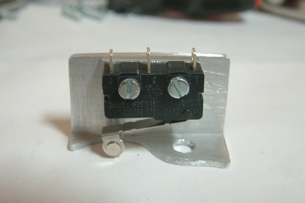
The third indicator light is for confirming the closure of
the landing brake. The mounting fixture for this limit switch is quite simple.
It consists of a short section (~1" length) of angle aluminum. I carved out a
small access hole area at the base of the angle aluminum for the plunger to make
contact to the limit switch. I added 3 more small holes of for the mounting
screws as shown.
Picture #2
The plunger for closing the limit switch is a small
aluminum rod with a threaded hole at one end. I replaced one of the 4 nuts, that
hold the landing brake actuator arm bracket, with this aluminum rod. As the
landing brake closes, the aluminum rod compresses the limit switch roller arm
and lights up indicator light.
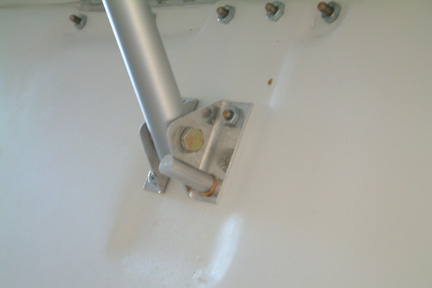
Picture #3
This picture shows the mounting location of the limit
switch. The entire actuator assembly and limit switch are covered by an
enclosure made in prior chapter.
Magnetometers
Together with the dual EFIS and dual AHRS, I also get two
(2) magnetometers. Per installation manual, mounting positions of the
magnetometers are critical. Briefly, they have to be away from ferrous metals
and electronic interference such as strobe lights etc. Some builders mounted
their magnetometers at the outboard cavities of their center section spar, while
others mount them at the luggage cavity next to the pilot/co-pilot seats. I
decided to mount mine at the luggage cavity next to the pilot/co-pilot seat
respectively. It is because the locations are away from most electronic
instruments, accessible for re-adjustment down the road (compared to the center
section spar) and shorter wires harness.
 With
the advancement of computers and electronic instrument in the aviation industry,
many round gauges, mechanical dial instruments are being replace by electronic
displays and accompanying gadgets - that include the traditional switch and
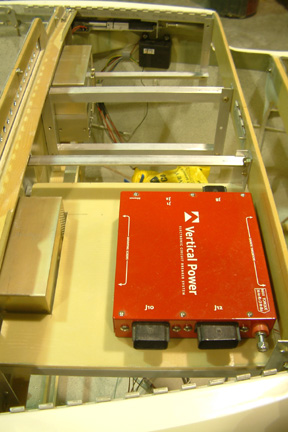
breaker panels. I have decided to install the Vertical Power Electronic Breakers
for Experimental Aircrafts. I decided on the VPX Pro system. Basically, its a
computer controlled power distribution and control system that replaces the many
switches and fuses on your Instrument Panel. It's somewhat of a new product and
I was not able to find many people that has first hand experience with it. In
fact, quite a few people express doubts with the system. However, you can read
about it at their web site.
With
the advancement of computers and electronic instrument in the aviation industry,
many round gauges, mechanical dial instruments are being replace by electronic
displays and accompanying gadgets - that include the traditional switch and
breaker panels. I have decided to install the Vertical Power Electronic Breakers
for Experimental Aircrafts. I decided on the VPX Pro system. Basically, its a
computer controlled power distribution and control system that replaces the many
switches and fuses on your Instrument Panel. It's somewhat of a new product and
I was not able to find many people that has first hand experience with it. In
fact, quite a few people express doubts with the system. However, you can read
about it at their web site.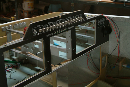 After
countless times of re-laying out my instrument panel, I eventually came to the
layout as shown. It also consists of a row of toggle switches that correspond to
the VPX Pro unit, in addition, I also has a row of LED indicator lights for
quick reference during landings and take-offs. These lights will be tied to
various limit switches. If you use Jack Wilhemson's nose lift, a limit switch is
already installed. All I have to do is to tie it to my indicator light. I plan
to add the same to my canopy lock, speed brake and fuel pump respectively. BTW,
the VPX system has a current fault option that I can assign to all electronic
instruments for in-flight monitoring as well.
After
countless times of re-laying out my instrument panel, I eventually came to the
layout as shown. It also consists of a row of toggle switches that correspond to
the VPX Pro unit, in addition, I also has a row of LED indicator lights for
quick reference during landings and take-offs. These lights will be tied to
various limit switches. If you use Jack Wilhemson's nose lift, a limit switch is
already installed. All I have to do is to tie it to my indicator light. I plan
to add the same to my canopy lock, speed brake and fuel pump respectively. BTW,
the VPX system has a current fault option that I can assign to all electronic
instruments for in-flight monitoring as well. 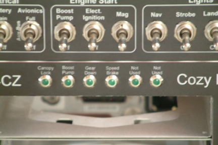 My IP panel consists of 6 indicator LED lights. The
purpose of the LED lights is to provide a quick reference (in additional to the
check list) on the status of several crucial components on the airplane. They
include:
My IP panel consists of 6 indicator LED lights. The
purpose of the LED lights is to provide a quick reference (in additional to the
check list) on the status of several crucial components on the airplane. They
include: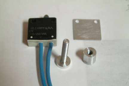

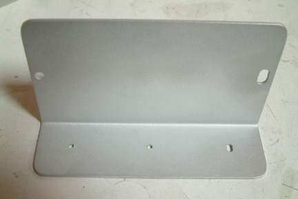 To mount the magnetometers, I made a couple L-shape
brackets as shown. The narrower side will be screwed against the side walls
inside the luggage cavity (next to the seat back). The magnetometers will be
bolted onto the top of the wider surfaces. The slotted holes (on both the
surfaces) are for aligning the magnetometers horizontally and vertically (per
GRT installation manual).
To mount the magnetometers, I made a couple L-shape
brackets as shown. The narrower side will be screwed against the side walls
inside the luggage cavity (next to the seat back). The magnetometers will be
bolted onto the top of the wider surfaces. The slotted holes (on both the
surfaces) are for aligning the magnetometers horizontally and vertically (per
GRT installation manual).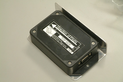 Here's
how I mounted my magnetometers.
Here's
how I mounted my magnetometers.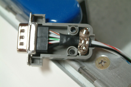 I
brought the wire harness for both from the AHRS down to the left cable duct
(inside the arm rest) past the seat back. From there, it exit the cable duct and
up along the back side of the seat back and up to the hole for the canopy lock.
The harness for the left magnetometer turns left while the harness for the right
routes through the shoulder support cavity and exit out the co-pilot luggage
cavity. The harnesses terminates to their respective 9 pin D-sub connectors.
I
brought the wire harness for both from the AHRS down to the left cable duct
(inside the arm rest) past the seat back. From there, it exit the cable duct and
up along the back side of the seat back and up to the hole for the canopy lock.
The harness for the left magnetometer turns left while the harness for the right
routes through the shoulder support cavity and exit out the co-pilot luggage
cavity. The harnesses terminates to their respective 9 pin D-sub connectors.