There are many types of Nav/Strobe lights available in the
general aviation market. LED Nav/Strobe lights were gaining its popularity when
I was getting close to Chapter 22 (Electrical). You can find a lot of discussions
in the Cozy forum on the pros and cons of each. I decided to go with LED Nav/Strobe
lights because they are quiet electrically (i.e. minimum noise interference to
other electrical devices such as radio communication) and less heat - at least
that's what I was told. After pondering a long time, I finally decided on AeroLED Pulsar NS Series P/N 11-1080C Nav/Strobe lights. The wirings for the
lights are simple and they do not require a controller. I tested them out on the
bench and the strobes lights are bright. If I am not done with wiring these
light by Christmas, I am tempted to hook them out outside my house and see if I
can drown out my neighbor's Christmas lights. If they do, then, my LED lights pass
the brightness test![]() .
.
Installing the Nav/Strobe Lights
|
|
You can see the insert before (right) and after (left) it is installed. Since I do not expect much of a push of pull force against the Nav/Strobe lights, I believe this is a good application for this type of inserts. |
|
The pencil mark shows the outline of the Nav/Strobe light foot print. I only use the two forward holes for securing the mounting bracket because I did not want to drill any hole close to the plies the holds the winglets. Besides, I plan to use RTV as a backup as well. |
Grounding the Nav/Strobe
Here's what I did, I drilled and tap a 4-40 threaded hole to the bottom tip of 'Y' arm as shown. If you look close, you can see I split the ground wire (black) from the light - one to the mounting bracket and the other to the Molex connector pin. From there, I bring the ground via the shield of the shielded wire cable to the mounting frame. |
|
Here's a picture of the Nav/Strobe lights after it is mounted. |
Aside from the grounding modifications I had to make for the Nav/Strobe lights, there are other aesthetic considerations. I have 4 wires coming from each wing tip (Nav, Strobe, Ground and Sync) plus 2 wires coming from each of the fuel sight gauge - a total of 10 wires. If I just tie them all together with traditional butt splice, I'll have a rather sizable lump of wires.
As a side note, I decided to tie the fuel gauge LED lights to the Nav lights because I do not see the need for a separate on/off switch for the fuel gauge lights. Chances are I'll need the fuel gauge lights when I need the Nav lights.
|
The 2 white wires are 3 conductor shield wires - one from the left wing tip and one from the right wing tip. All 6 conductor wires (2 Nav, 2 strobe, 2 Sync) plus 2 shielding (ground) are terminated to the D-sub conncetor - using up 8 of the 15 pin connector. Note the 2 black wire are the shielding-to-D-sub pins techniques from Aeroelectric as well. |
|
|
|
|
Landing Lights
|
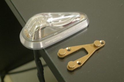 My Nav/Strobe lights come with a mounting bracket which
allows the attachment/removal of the light component as necessary. The challenge is to
attach the mounting bracket to the wing tips. I searched through the Cozy archives
and inquired on methodologies in the Cozy forum. Surprisingly, many builders just RTV their lights to the wing tip with no
mechanical means. With 200 mph wind blowing
against the lights, I am just a bit concerned about it - probably overly
conservative. Nut plates are not a good option because there's hardly any room to get
to the inside of the wing tip to squeeze the rivets in place. A blind rivet will
leave a raised head, thus preventing the mounting bracket to sit flush to the
surface of the wing tip.
My Nav/Strobe lights come with a mounting bracket which
allows the attachment/removal of the light component as necessary. The challenge is to
attach the mounting bracket to the wing tips. I searched through the Cozy archives
and inquired on methodologies in the Cozy forum. Surprisingly, many builders just RTV their lights to the wing tip with no
mechanical means. With 200 mph wind blowing
against the lights, I am just a bit concerned about it - probably overly
conservative. Nut plates are not a good option because there's hardly any room to get
to the inside of the wing tip to squeeze the rivets in place. A blind rivet will
leave a raised head, thus preventing the mounting bracket to sit flush to the
surface of the wing tip.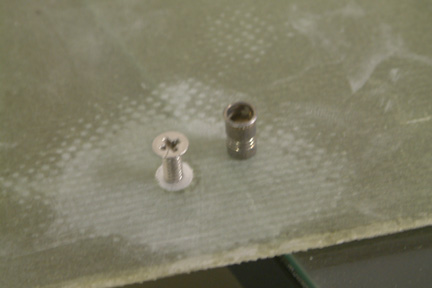 I found a rivet nut insert from McMaster-Carr
 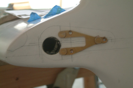 My
next step is to position the mounting bracket onto the wing tips. Instead of
using the wire pass-thru hole as a reference, it is more logical to use their
respective wing tips as a reference. For my own record, the tip of my Nav lights
is 1.75" from the forward edge of the wing tips. This distance provides the best
coverage over the wire pass-thru holes while maintaining identical Nav/Strobe
positions relative to the wing tips.
My
next step is to position the mounting bracket onto the wing tips. Instead of
using the wire pass-thru hole as a reference, it is more logical to use their
respective wing tips as a reference. For my own record, the tip of my Nav lights
is 1.75" from the forward edge of the wing tips. This distance provides the best
coverage over the wire pass-thru holes while maintaining identical Nav/Strobe
positions relative to the wing tips.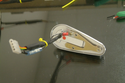 The grounding instructions are more for the metal
airframes than for the Cozy. So I have to improvise a bit. I was surprised to
learned from the VansAirforce forum that these lights are not internally
grounded. The instruction requires the 'black' wire from the light to be
attached to the mounting structure/frame (i.e. to ground). In our case, the
mounting structure is attached to our wing tip of composite materials - no
ground. In addition, the way I attach my mounting frame provides no room to
attach a wire lug. I have to make some modification to the original mounting 'Y"
frame.
The grounding instructions are more for the metal
airframes than for the Cozy. So I have to improvise a bit. I was surprised to
learned from the VansAirforce forum that these lights are not internally
grounded. The instruction requires the 'black' wire from the light to be
attached to the mounting structure/frame (i.e. to ground). In our case, the
mounting structure is attached to our wing tip of composite materials - no
ground. In addition, the way I attach my mounting frame provides no room to
attach a wire lug. I have to make some modification to the original mounting 'Y"
frame.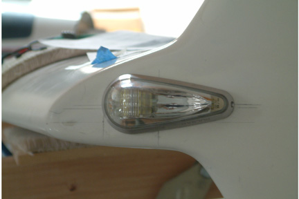
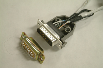 I
learned this wiring techniques from Aeroelectric - Shield Termination
Techniques. Instead of joining the selective wires using butt splicing or direct
soldering, I terminated all the wires (using D-sub pins) to a male D-sub
connector. Then I made the joining via the female D-sub connector. Here's a
picture with all the power, ground and sync wires going into the male D-sub
connector.
I
learned this wiring techniques from Aeroelectric - Shield Termination
Techniques. Instead of joining the selective wires using butt splicing or direct
soldering, I terminated all the wires (using D-sub pins) to a male D-sub
connector. Then I made the joining via the female D-sub connector. Here's a
picture with all the power, ground and sync wires going into the male D-sub
connector.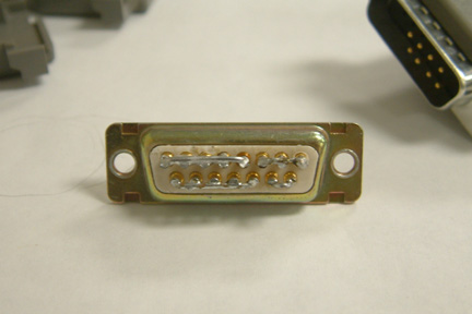 A
female D-sub connector is used to join the corresponding wires as shown. I used
a 18 gauge solid wire to join all the appropriate connections and soldered them
in place. The female plug is, in a way, the networking plug.
A
female D-sub connector is used to join the corresponding wires as shown. I used
a 18 gauge solid wire to join all the appropriate connections and soldered them
in place. The female plug is, in a way, the networking plug.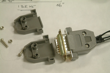 Here's
a picture showing the connection assembly when completed. All the incoming and
out-going wires came through the male D-sub connector. There's no wire coming
out of the female (network) plug. If I un-plug the female plug, all connections
will be disabled.
Here's
a picture showing the connection assembly when completed. All the incoming and
out-going wires came through the male D-sub connector. There's no wire coming
out of the female (network) plug. If I un-plug the female plug, all connections
will be disabled. 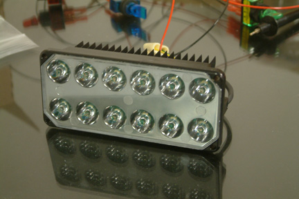 I installed my landing light in Chapter 13 Section 5.
It was a low cost halogen light for pick up trucks. As
time passed throughout my building process, LED landing lights were coming into
light, so to speak. While I was getting the AeroLED Nav/Strobe, I decided to
change out my initial halogen landing light with their AeroSun
Landing/Taxi/Recognition lights P/N 01-2120.
I installed my landing light in Chapter 13 Section 5.
It was a low cost halogen light for pick up trucks. As
time passed throughout my building process, LED landing lights were coming into
light, so to speak. While I was getting the AeroLED Nav/Strobe, I decided to
change out my initial halogen landing light with their AeroSun
Landing/Taxi/Recognition lights P/N 01-2120.