Oil Check Door
 The
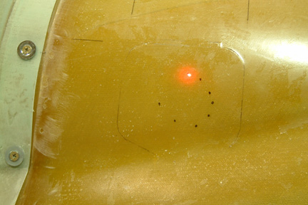
next step is the oil check door. Though it is pre-marked with the Featherlite
cowling, I like to make sure the door is at the appropriate location before
cutting. I tied a laser pointer along side of the oil check tube and project a
dot onto the under side of the top cowling. By rotating the laser pointer around
the oil check tube, a partial circle is drawn.
The
next step is the oil check door. Though it is pre-marked with the Featherlite
cowling, I like to make sure the door is at the appropriate location before
cutting. I tied a laser pointer along side of the oil check tube and project a
dot onto the under side of the top cowling. By rotating the laser pointer around
the oil check tube, a partial circle is drawn.
According to Plan, the oil check door is to be cut from
the top cowling and re-used. Since the cut will be on a curve surface (especially
the lower right corner), a poor cut around the corners will end up with a wide
seam. I decided to make a backup door as insurance. I pre-marked the
door location and covered it up with packing tape. Then I laid up 6 ply BID over the
door area. Once cured, I popped it off for future use. The effort was pretty
simple and straight forward.
I followed the Plans and completed the oil check door
without much problem. I used a combination of my Fein Tool and Jig Saw to
complete the cut. The seams are not perfect, however, the fill and sand stage
will probably do the job. I did not have to use the backup door at this time.
 I
bought my cowling from Featherlite per Plans' recommendation. It arrived about
30 days later in a big box. It consists of three parts - the top, bottom and a
stiffener for the top cowl. I measured the width of the lip at the forward edge
of the cowl - it was not uniform. With a long sanding block, an electric hand
sander and ~30 minutes, I have a uniform forward lip of 1 3/8" in width.
I
bought my cowling from Featherlite per Plans' recommendation. It arrived about
30 days later in a big box. It consists of three parts - the top, bottom and a
stiffener for the top cowl. I measured the width of the lip at the forward edge
of the cowl - it was not uniform. With a long sanding block, an electric hand
sander and ~30 minutes, I have a uniform forward lip of 1 3/8" in width.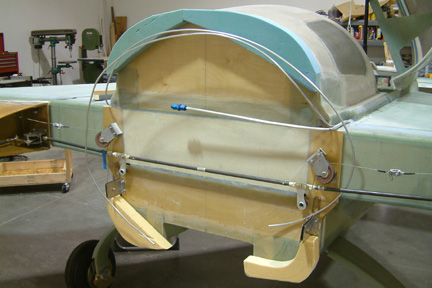 I
scrounged several 2" foam blocks (scraps) and cut them to appropriate
sizes. With 3 to 4 dabs of 5 min. epoxy, I glued them to the firewall per
Plan. Then I sanded their edges flush against the firewall.
I
scrounged several 2" foam blocks (scraps) and cut them to appropriate
sizes. With 3 to 4 dabs of 5 min. epoxy, I glued them to the firewall per
Plan. Then I sanded their edges flush against the firewall. 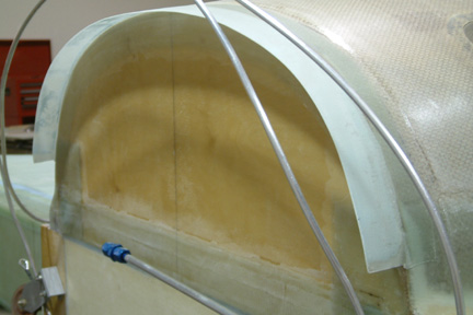 After
cure, removing the foam was not too troublesome either. I used a small wood
strip and marked off 1.5" along the entire length of the lip. Then I trimmed and
sanded to dimension.
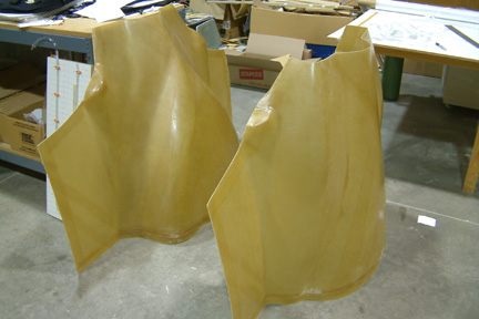
After
cure, removing the foam was not too troublesome either. I used a small wood
strip and marked off 1.5" along the entire length of the lip. Then I trimmed and
sanded to dimension.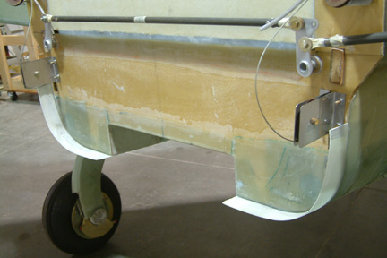 Here's
a picture of the lower lips.
Here's
a picture of the lower lips.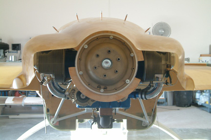 There
is supposed to be a 1 1/4" spacing between the cowling and the engine gear hub
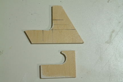
per Plan. I
made a template (out of a wood board) and bolted it onto the gear hub. This template helps to
support and align the upper cowling prior to mounting.
There
is supposed to be a 1 1/4" spacing between the cowling and the engine gear hub
per Plan. I
made a template (out of a wood board) and bolted it onto the gear hub. This template helps to
support and align the upper cowling prior to mounting.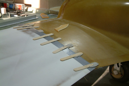 The
supporting lips along the wing root and aft strake were pretty straight forward
per Plan. Here's a picture for holding the cowling level with the wing root.
The first set of plies (5 layers) were easily accomplished. The subsequent
supporting (single) layer, however, was a bit more
challenging because it has to wrap around a sharp corner. It turned out that
peel-ply (Per Plan) and patience did the trick.
The
supporting lips along the wing root and aft strake were pretty straight forward
per Plan. Here's a picture for holding the cowling level with the wing root.
The first set of plies (5 layers) were easily accomplished. The subsequent
supporting (single) layer, however, was a bit more
challenging because it has to wrap around a sharp corner. It turned out that
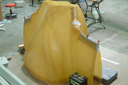
peel-ply (Per Plan) and patience did the trick.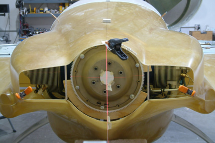 With the upper cowling mounted, I proceeded to install the
lower cowling. It was a bit more challenging than expected because gravity is
working against you. A bit of sag here, and bit of sag there...while you are
stooping under the wings looking up. I tried many tricks (to hold up the lower
cowling) which allowed me to keep the cowling in place for precise mounting. they
included the laser cross-hair, a plum, masking tape on the plum line to
establish the center and lower cowl lip position, and a cross-hair taped at the
center of the engine.
With the upper cowling mounted, I proceeded to install the
lower cowling. It was a bit more challenging than expected because gravity is
working against you. A bit of sag here, and bit of sag there...while you are
stooping under the wings looking up. I tried many tricks (to hold up the lower
cowling) which allowed me to keep the cowling in place for precise mounting. they
included the laser cross-hair, a plum, masking tape on the plum line to
establish the center and lower cowl lip position, and a cross-hair taped at the
center of the engine.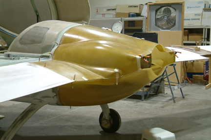
 My
prop extension arrived (from Saber Manufacturing) and it is a very nice machine
part. I was alerted by Sam (the owner) that it has a very tight tolerance fit.
I may have to rotate the prop extension, just to find the perfect fit. I tried
all six possible positions with no avail. I finally slid all 6 bolts through
the prop extension and allowed them to guide me along. It worked! I hand turned
the bolts at 1-4-6-3-5-2 sequence (a slight turn at a time) until the forward
face of the extension met the gear plate.
My
prop extension arrived (from Saber Manufacturing) and it is a very nice machine
part. I was alerted by Sam (the owner) that it has a very tight tolerance fit.
I may have to rotate the prop extension, just to find the perfect fit. I tried
all six possible positions with no avail. I finally slid all 6 bolts through
the prop extension and allowed them to guide me along. It worked! I hand turned
the bolts at 1-4-6-3-5-2 sequence (a slight turn at a time) until the forward
face of the extension met the gear plate. 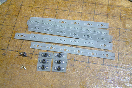 Between the top and bottom cowl, I used a total of 49 nut
plates to hold them to the fuselage, wing root and each other - that's a lot of
nut plates. The Plan suggested camloc fasteners in some but not all locations. I
figure if I have to remove a bunch of screws from those nut plates, I may as
well get a powerful electric screwdriver and remove them all.
Between the top and bottom cowl, I used a total of 49 nut
plates to hold them to the fuselage, wing root and each other - that's a lot of
nut plates. The Plan suggested camloc fasteners in some but not all locations. I
figure if I have to remove a bunch of screws from those nut plates, I may as
well get a powerful electric screwdriver and remove them all.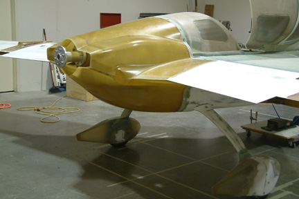
 The
scoop lip was not too difficult. I made a couple wood templates to shape the
scoop. The top template was used to round off the bottom edge of the scoop
first. Then I used the second template to complete the rounded 5/8" lip at the
forward edge. I followed the Plan for making the rest of the air scoop.
The
scoop lip was not too difficult. I made a couple wood templates to shape the
scoop. The top template was used to round off the bottom edge of the scoop
first. Then I used the second template to complete the rounded 5/8" lip at the
forward edge. I followed the Plan for making the rest of the air scoop.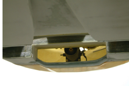 Here's
a picture of the completed scoop lip.
Here's
a picture of the completed scoop lip.