Shaping the Lower Strake Fairings
 The
lower strake fairings are made to cover up / blend in the fuel sump under the
strakes. Since this is not a structural or shape critical part, you can see more
variations among Cozy builders than you can count with your fingers and toes! I
decided to follow the Plans recommendations as close as possible. Actually, I
followed Nat's fairings (per the Plan's picture at the back of the Chapter).
However, I did not carve out the fairings from a bunch of foam blocks.
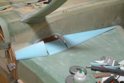
Instead, I followed
Norm Muzzy's approach by hot wiring them out from a block of blue wing foam.
Since the Feather Lite's sump is somewhat straight in the middle section but
curved at both ends (like a lemon wedge), I decided to divide the fairing into
three different sections as shown.
The
lower strake fairings are made to cover up / blend in the fuel sump under the
strakes. Since this is not a structural or shape critical part, you can see more
variations among Cozy builders than you can count with your fingers and toes! I
decided to follow the Plans recommendations as close as possible. Actually, I
followed Nat's fairings (per the Plan's picture at the back of the Chapter).
However, I did not carve out the fairings from a bunch of foam blocks.
Instead, I followed
Norm Muzzy's approach by hot wiring them out from a block of blue wing foam.
Since the Feather Lite's sump is somewhat straight in the middle section but
curved at both ends (like a lemon wedge), I decided to divide the fairing into
three different sections as shown.
 I started with the carpenter's widget and extracted the
surface profile of the sump. since the profile has ridges and valleys, I rounded
it off with my graphics software. I also measured the angle between the fuselage sides to
the bottom of the strake - its greater than 90 degrees. Remember the bottom of the strake
slopes up from the wing root to the wing tip? Connecting the angled sides to the sump profile,
a pair of hot wire templates can be made. I made two (2) for both ends of the center section.
the picture shows the 2 templates for the mid section and the end template. The mid section
foam is about 7 1/2" in length.
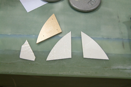
I started with the carpenter's widget and extracted the
surface profile of the sump. since the profile has ridges and valleys, I rounded
it off with my graphics software. I also measured the angle between the fuselage sides to
the bottom of the strake - its greater than 90 degrees. Remember the bottom of the strake
slopes up from the wing root to the wing tip? Connecting the angled sides to the sump profile,
a pair of hot wire templates can be made. I made two (2) for both ends of the center section.
the picture shows the 2 templates for the mid section and the end template. The mid section
foam is about 7 1/2" in length.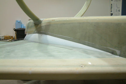 After
carving a cavity in all three sections to accommodate the features of the sump,
I 5-min. epoxied all three sections in place. Then I sanded the entire
fairing for a smooth flow. After micro and patching up all the dents in the
foam, I glassed both fairings with 2 layers of BID. I was able to stretch a
single strip of BID to cover the entire length of the fairing.
After
carving a cavity in all three sections to accommodate the features of the sump,
I 5-min. epoxied all three sections in place. Then I sanded the entire
fairing for a smooth flow. After micro and patching up all the dents in the
foam, I glassed both fairings with 2 layers of BID. I was able to stretch a
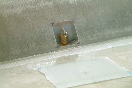
single strip of BID to cover the entire length of the fairing.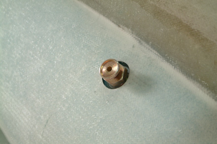 After
cure, I located the pre-marked hole location (on the foam). Then I drilled and sanded a tight fit opening for the fuel drain value.
The size of the hole was large enough to accommodate the diameter of a socket
wrench.
After
cure, I located the pre-marked hole location (on the foam). Then I drilled and sanded a tight fit opening for the fuel drain value.
The size of the hole was large enough to accommodate the diameter of a socket
wrench.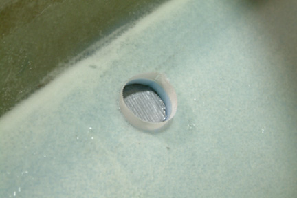 After
the opening was rounded off nicely, I removed the fuel drain valve, re-capped the
opening with duct tape (to keep the dirt out), then applied wet flox all along the
gap inside the hole and peel-plied.
After
the opening was rounded off nicely, I removed the fuel drain valve, re-capped the
opening with duct tape (to keep the dirt out), then applied wet flox all along the
gap inside the hole and peel-plied. 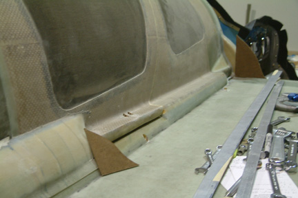 Based
on my limited experience with pour foam, I doubted I could sand down a
symmetrical set of upper fairings by hand. I think I can do a better job by hot
wiring instead. I started by making a hot wire template for the fairing 'ears'
both front and back. Then I nailed them at both ends of the blue foam and cut
out the fairing core.
Based
on my limited experience with pour foam, I doubted I could sand down a
symmetrical set of upper fairings by hand. I think I can do a better job by hot
wiring instead. I started by making a hot wire template for the fairing 'ears'
both front and back. Then I nailed them at both ends of the blue foam and cut
out the fairing core. 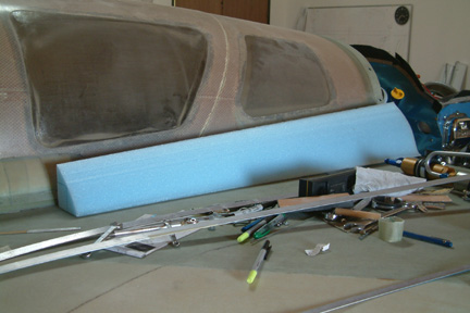 Here's the hot wire result. Note that the foam cut out is
solid at the core, therefore, I have to hollow it out to fit around the canopy
and turtle back lip (as shown in the above picture).
Here's the hot wire result. Note that the foam cut out is
solid at the core, therefore, I have to hollow it out to fit around the canopy
and turtle back lip (as shown in the above picture).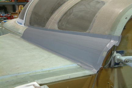 Note
that I have Princeton fuel probes mounted on hard points - right above the
fuel sump opening and inside the foam cores (both pilot and passenger sides). My
concern is accessibility down the road? Most builders told me that these probes
hardly fail and that they plan to dig it out when the time comes (if ever). I was
not comfortable with that thought and decided to build in a fall back access
door for them.
Note
that I have Princeton fuel probes mounted on hard points - right above the
fuel sump opening and inside the foam cores (both pilot and passenger sides). My
concern is accessibility down the road? Most builders told me that these probes
hardly fail and that they plan to dig it out when the time comes (if ever). I was
not comfortable with that thought and decided to build in a fall back access
door for them.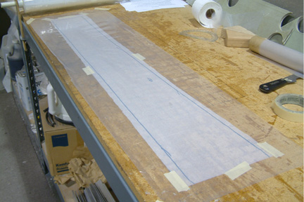
 Once
the fairings are cured, I stuck packing tape at the fuel probe location and made
an additional 4 layer BID cover (approx. 3" x 3") - as shown in the picture.
This will eventually be my access door.
Once
the fairings are cured, I stuck packing tape at the fuel probe location and made
an additional 4 layer BID cover (approx. 3" x 3") - as shown in the picture.
This will eventually be my access door.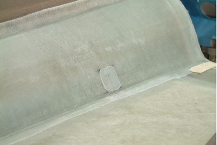 Once
cut, I slapped the access door BID back in place and traced the window
pattern onto it. After cutting and trimming, I ended up with a seamless access door for my
fuel probes.
Once
cut, I slapped the access door BID back in place and traced the window
pattern onto it. After cutting and trimming, I ended up with a seamless access door for my
fuel probes. 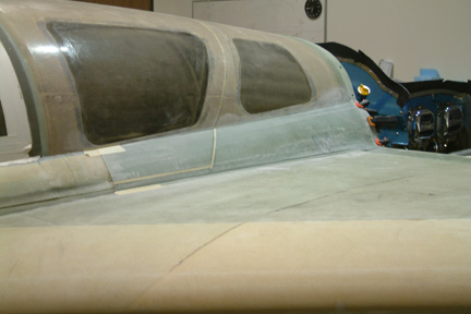 Here's
a picture of the pilot side upper fairing. Notice the masking tape for cutting
the fairing into the strake section and the canopy section.
Here's
a picture of the pilot side upper fairing. Notice the masking tape for cutting
the fairing into the strake section and the canopy section.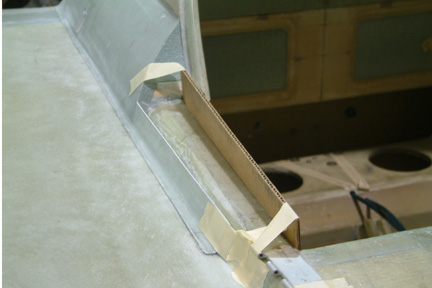 Once
I cut the fairing into its appropriate sections (shown left), the challenge is
to blend the fairing with the rest of the fuselage.
Once
I cut the fairing into its appropriate sections (shown left), the challenge is
to blend the fairing with the rest of the fuselage. 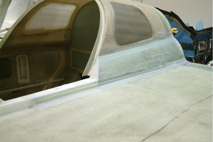 Once
the foam cured, I reshaped and glassed. I did the same for the pilot side as
well.
Once
the foam cured, I reshaped and glassed. I did the same for the pilot side as
well.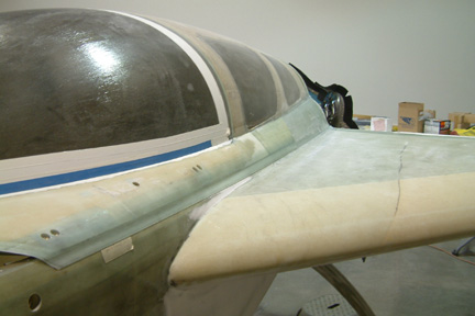 As
for the forward end of the upper fairings, I tackled the pilot side first
because it going to be easier than the hinge side. I used a bit of pour foam and
micro for shaping. I also extended the canopy lip (~3/4") down the pilot side of
the fuselage. The intent of the extension is to help the sealing of the cockpit
besides the sealing tape. Incidentally, it also helps to keep the canopy in
position.
As
for the forward end of the upper fairings, I tackled the pilot side first
because it going to be easier than the hinge side. I used a bit of pour foam and
micro for shaping. I also extended the canopy lip (~3/4") down the pilot side of
the fuselage. The intent of the extension is to help the sealing of the cockpit
besides the sealing tape. Incidentally, it also helps to keep the canopy in
position.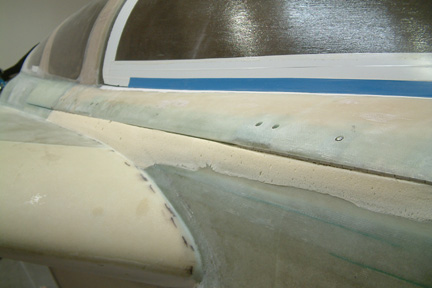 Making
a nice seam on the hinge side was difficult because of the position of the
forward hinge and the way the canopy opens. In addition, my original canopy edge
is kinda crappy (picture left). You can see my hinges are showing and the canopy
edge is crooked. I made a couple of attempts but was not successful. Notice the
pour foam along the side the fuselage? That was one of those approaches.
Making
a nice seam on the hinge side was difficult because of the position of the
forward hinge and the way the canopy opens. In addition, my original canopy edge
is kinda crappy (picture left). You can see my hinges are showing and the canopy
edge is crooked. I made a couple of attempts but was not successful. Notice the
pour foam along the side the fuselage? That was one of those approaches.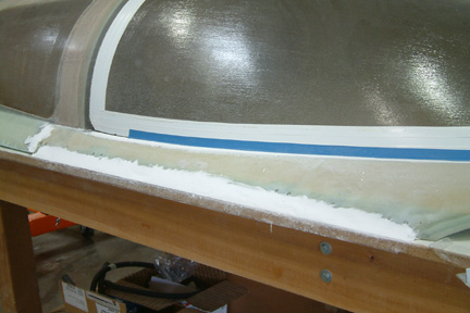 I
removed the canopy and sat it flat on the table. Then put packing tape along the
edge of the table. Then I used extra hinge halves to fill the open knuckle of
the hinges, covered them with electrical tape, and packed the entire canopy edge
(including hinges) with West micro.
I
removed the canopy and sat it flat on the table. Then put packing tape along the
edge of the table. Then I used extra hinge halves to fill the open knuckle of
the hinges, covered them with electrical tape, and packed the entire canopy edge
(including hinges) with West micro.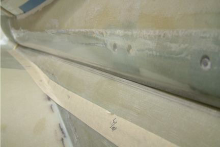 One
of the toughest tasks is to open the canopy (a bit at a time) and sand off the
excess micro - to make sure the canopy swings freely. Fortunately for me, I have
a remote actuator control canopy (ref. Chapter 18 Section 22A). This allows
me to raise and lower the canopy remotely while I pay close attention to any
obstruction.
One
of the toughest tasks is to open the canopy (a bit at a time) and sand off the
excess micro - to make sure the canopy swings freely. Fortunately for me, I have
a remote actuator control canopy (ref. Chapter 18 Section 22A). This allows
me to raise and lower the canopy remotely while I pay close attention to any
obstruction.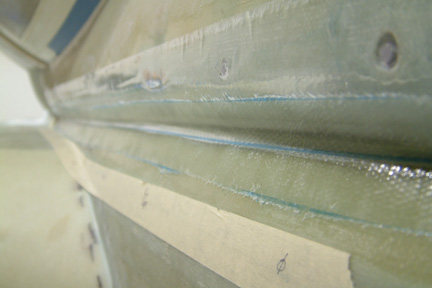 My
next step was to build up a fence to hide the seam along the canopy. This is one
of those areas most Cozy builders find challenging. After observing how the
canopy edge 'swings' as it opens and closes, I decided to put a 2 layer BID
with the canopy at open position. This forms the 'inner' surface of the fence.
My
next step was to build up a fence to hide the seam along the canopy. This is one
of those areas most Cozy builders find challenging. After observing how the
canopy edge 'swings' as it opens and closes, I decided to put a 2 layer BID
with the canopy at open position. This forms the 'inner' surface of the fence.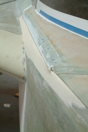 After
the fence is trimmed, I added pour foam to 'fill in' and match up the fuselage
curvature.
Since the forward edge of my hinge sticks out past the fuselage (per Plan), I
decided to use a bit more foam to blend it in - at least to the first knuckle.
It turned out I have to 'extend' my blending past the hinge a bit (shown left).
After
the fence is trimmed, I added pour foam to 'fill in' and match up the fuselage
curvature.
Since the forward edge of my hinge sticks out past the fuselage (per Plan), I
decided to use a bit more foam to blend it in - at least to the first knuckle.
It turned out I have to 'extend' my blending past the hinge a bit (shown left).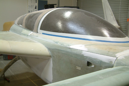 Here's
a picture of my completed fairing and seam. So far, I have only done the
pre-fill. A final fill on the entire canopy and fuselage shall be performed in
Chapter 25. I intentionally left this picture the original size because it is
difficult to see the seam line.
Here's
a picture of my completed fairing and seam. So far, I have only done the
pre-fill. A final fill on the entire canopy and fuselage shall be performed in
Chapter 25. I intentionally left this picture the original size because it is
difficult to see the seam line.