Chapter
9 - Section 7
Sam James Wheel Pants & Matco Brakes
I did not start on the wheel pants until I got to chapter
23...may be because it was not in the Plans. But then, I do not recall what got
me started on the pants at this time. Anyway, in hindsight, these wheel pants
took a lot more work than expected and I spent many hours in trials and errors -
just to make it fit reasonable well, not very or exceptional well...I was told,
by a Cozy builder, that's why retractable gear was developed .
.
|
Sam James Wheel Pants |
|
 Past builders have shown that adding a set of wheel pants
gains ~10 mph and I decided to add mine at this time. There is a set of wheel
pant molds getting passed around among Cozy builders. I placed my name on the
waiting list until I saw a picture of the mold. That thing is huge! With
multiple wheel pants sources (reasonable price tags to boot) on the market, I
figure it is much cheaper
to buy than to make them. I decided on Sam James wheel pants because it was
originally designed by Gary Hertzler (an aerodynamic speed guru). Though a few
Cozy builders warned that the Sam James wheel pants are too narrow for our Matco
brakes, there were some successes. I decided to take the challenge and go for
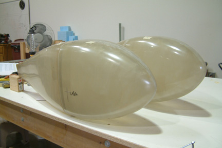
the best design...The wheel pants arrived within a couple weeks after I
placed the order. They came in front and back halves. The total cost
was $245 including shipping. I cannot imagine saving much $ by building my own.
The wheel pants have nice smooth surfaces, except for its joining seams and
matching edges. It took me a couple
of hours to sand the seams flush to the surfaces. I had to fix up the matching
edges during the finishing process. There are two cross-hairs drawn on the
front halves (opposite sides) of the pants indicating the inboard & outboard axle locations. Unfortunately, when I
put a laser cross-hair to check its positional accuracy (square-ness), its off by a good 3/8". I believe
the cross-hair basically identifies the maximum height location of the wheel pants.
Naturally, that's where you want the axle (i.e. the highest point of the wheels).
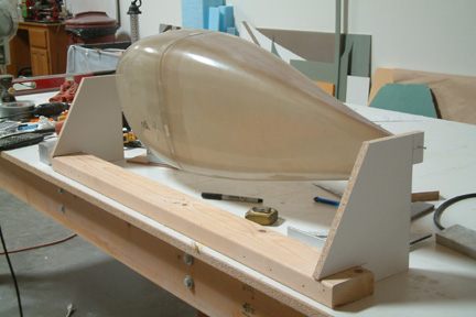
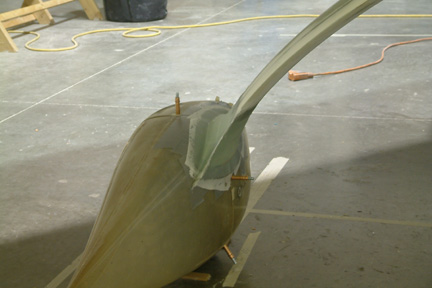
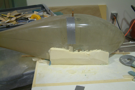
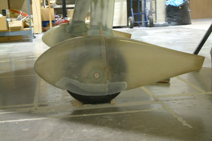
Picture shows the wheel pants after I cleaned up the rough edges. The
installation directions from Sam James was for an RV and does not really apply to
a Cozy installation. The only useful information is that the wheel pants are
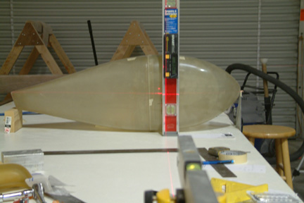
at level position if I raise its aft end 3 1/2". To be sure, I confirmed
this with Sam of Sam James. Notice the 2x4 wood blocks (3 1/2" high) at
the aft end of the pants? Also, the cross-hairs (pre-marked on the pants) show
the horizontal and vertical levels of the wheel pants. Past builders have shown that adding a set of wheel pants
gains ~10 mph and I decided to add mine at this time. There is a set of wheel
pant molds getting passed around among Cozy builders. I placed my name on the
waiting list until I saw a picture of the mold. That thing is huge! With
multiple wheel pants sources (reasonable price tags to boot) on the market, I
figure it is much cheaper
to buy than to make them. I decided on Sam James wheel pants because it was
originally designed by Gary Hertzler (an aerodynamic speed guru). Though a few
Cozy builders warned that the Sam James wheel pants are too narrow for our Matco
brakes, there were some successes. I decided to take the challenge and go for
the best design...The wheel pants arrived within a couple weeks after I
placed the order. They came in front and back halves. The total cost
was $245 including shipping. I cannot imagine saving much $ by building my own.
The wheel pants have nice smooth surfaces, except for its joining seams and
matching edges. It took me a couple
of hours to sand the seams flush to the surfaces. I had to fix up the matching
edges during the finishing process. There are two cross-hairs drawn on the
front halves (opposite sides) of the pants indicating the inboard & outboard axle locations. Unfortunately, when I
put a laser cross-hair to check its positional accuracy (square-ness), its off by a good 3/8". I believe
the cross-hair basically identifies the maximum height location of the wheel pants.
Naturally, that's where you want the axle (i.e. the highest point of the wheels).
Picture shows the wheel pants after I cleaned up the rough edges. The
installation directions from Sam James was for an RV and does not really apply to
a Cozy installation. The only useful information is that the wheel pants are
at level position if I raise its aft end 3 1/2". To be sure, I confirmed
this with Sam of Sam James. Notice the 2x4 wood blocks (3 1/2" high) at
the aft end of the pants? Also, the cross-hairs (pre-marked on the pants) show
the horizontal and vertical levels of the wheel pants.
|
[Hindsight] Installation of
these wheel pants took a lot more work than expected and you will be crawling
under the plane's arm pits on your knees countless times. So do your knees a
favor and have a set of knee pads handy. Due to the tight fit of the pants, I
have tried and eventually discarded several attachment approaches. Ultimately,
my wheel pants are a bit more chopped up than it needs to be for clearance, but I'll
leave it the way it is for now. Maybe one day I'll change them out. Will see...
[More Hindsight] Due to the
size and shape of Sam James wheel pants, I can't see installing them without
some form of modification to the original pants. I know of three different
versions (including mine) to make it work. So, before you decide on Sam James
wheel pants, check out the various approaches on the Cozy Builders sites - you
may not want to venture into these extra modifications...
|
Determine Wheel Pant Dimensions |
|
 In
order to mount the wheel pants at the appropriate location, I must first figure out
its various critical dimensions. Unfortunately, the wheel pants do not match
up too well (front and back) and are somewhat flexible in shape. In
order to mount the wheel pants at the appropriate location, I must first figure out
its various critical dimensions. Unfortunately, the wheel pants do not match
up too well (front and back) and are somewhat flexible in shape.
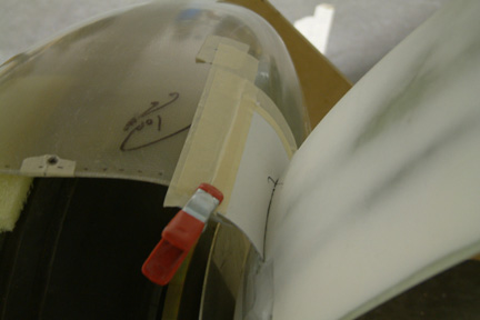
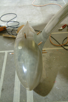
I drew a straight line on my work bench perpendicular to
its edge. Then I clamped a flat, vertical plate against the edge of the work bench,
with its edge lined up to the perpendicular line I just drew. If you look close at the forward tip of the
wheel pant, you can barely see the plate with a small piece of masking tape. I placed the wheel pant over
the center line and butt its nose against my flat plate surface. I drew a line on
the 2x4 wood block and lined it up along the center line as well. Then I rested the
aft end of the wheel pants on top of the wood block (as shown).
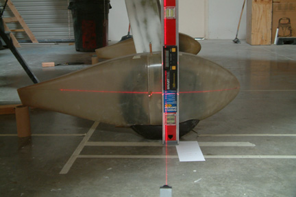
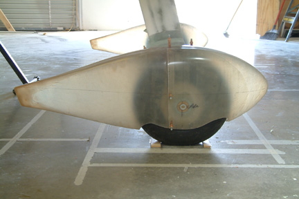
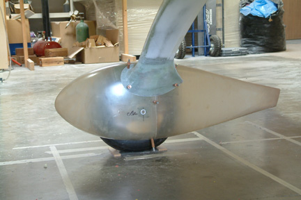
Using my crosshair laser and my digital level (standing
on end at 90o), I can establish the foremost point of my wheel pants
and its leveled aft end position as well. It turned out that the nose tip is
level with the upper tip of the tail (shown). This is an important dimension because
the wheel pants need to be mounted to a pre-determined angle relative to the fuselage.
I also confirmed my laser level lined up to the pre-marked cross-hairs.
Once I got the wheel pants lined up, I used a couple dabs
of hot glue to hold the two halves in place. Then I drilled and attached them better with 3 clecos each
for now.
|
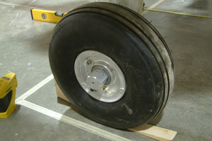
Here's some of the dimensions I got with my set of Sam
James Pants and Matco Brakes/Tires:
- Maximum height (pants) = 12"
- Inside width (pants) = 8.5"
- Height of forward tip of pants above floor = 6.375"
- Maximum tire height = 13.25"
- Width between outboard of tire to inboard axle mounting
plate = 7.5".
As you can see, the bottom of the pants will be 1.625" (13
1/4 + 3/8 - 12) above ground - the pants seem a bit short to me. However, the
width of the pants seems to be adequate to accommodate the Matco brakes - don't
know the reason for the warning from some Cozy builders? Guess I will find out in good time...
Wheel Pants Mounting Criteria
Before the mounting process, I visited the Cozy archives
and talked to a few Cozy builders regarding instructions and the do's and
don'ts. Here's what I gathered for the mounting criteria:
 |
Wheel pants should be parallel to the wheels / center
line of the fuselage. Technically, they are not the same. Remember when you
mount the wheels, its supposed to be .4 degree toe in, but they are so close to
the wheels, it will be hard to tell. Regardless, I decided to set the pants
parallel to the fuselage because its more critical in flight; |
|
The maximum height location of the wheel pants should line up to
the wheel axle because that's where the highest point of the tire is located;
|
|
There should be a clearance of ~3/8" between the top of
the tire and pants; |
|
Horizontal level of pants should be ~2o nose
down relative to fuselage level; |
|
There should be a minimum of 1/4" clearance between tire
sides and pants sides (Cozy archives indicated 1/2" - 1").
|
|
Wheel Pants Anchor Nut & Outboard Attach
Point |
|
 The
wheel pants need to be bolted in place once they are seated. Van's
Aircraft sells a wheel nut that is a combination of wheel nut (replace our Matco
brake axle nut) and wheel pant nut plate for $14 each. It is a worthwhile
purchase because it helps in mounting the pants and eliminates the need for
drilling and tapping into the end of our Matco axle. The
wheel pants need to be bolted in place once they are seated. Van's
Aircraft sells a wheel nut that is a combination of wheel nut (replace our Matco
brake axle nut) and wheel pant nut plate for $14 each. It is a worthwhile
purchase because it helps in mounting the pants and eliminates the need for
drilling and tapping into the end of our Matco axle.
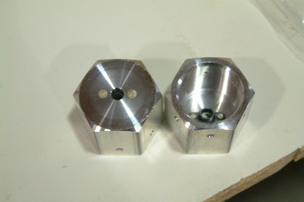
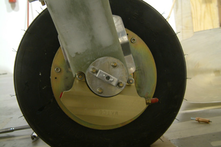
Without further ado, I replaced my original axle nuts with
the new pair. I used a straight edge and measured the protrusion of the new
anchor nuts from the surface of the tires. It turned out to be 9/16". That
means, if I bolt the outboard face of my wheel pants to the face of these anchor
nuts, I should have 9/16" spacing between the side of the tires and wheel pants.
[Hindsight] Wayne
Hicks pointed out to the group that the flat surface of the Van's Axle nuts may
not be able to keep the washer centered. If that occurs, the washer may rub
against the wheel hub - a potential hazardous situation - a good observation and
good call!
|
|
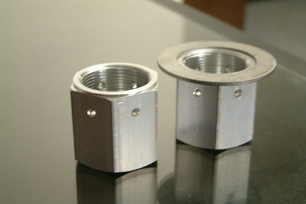 To
counter that safety issue, I took the axle nuts and turned a groove at the
contact surface just enough fit into the ID of the washer, yet just a hair less
than the thickness of the washer, thus keeping it from
moving 'out of center'. To
counter that safety issue, I took the axle nuts and turned a groove at the
contact surface just enough fit into the ID of the washer, yet just a hair less
than the thickness of the washer, thus keeping it from
moving 'out of center'.
|
|
Establish Aircraft Center Line |
|
 I raised the nose of the fuselage to 2o up. I
assume its the standard cruising configuration. I also hot glued a couple of
wood blocks between the wheels to keep the plane from moving. Then I dropped a
plumb line from the (aircraft) nose tip and firewall centerline onto the floor.
With masking tape and laser, I drew the center line of the fuselage on the floor
below. With a cross-hair
laser, I projected a perpendicular line from the center line to the back of both
wheels. With the cross-hair laser again, I projected another line along the side of
the wheels and parallel to the center line. I raised the nose of the fuselage to 2o up. I
assume its the standard cruising configuration. I also hot glued a couple of
wood blocks between the wheels to keep the plane from moving. Then I dropped a
plumb line from the (aircraft) nose tip and firewall centerline onto the floor.
With masking tape and laser, I drew the center line of the fuselage on the floor
below. With a cross-hair
laser, I projected a perpendicular line from the center line to the back of both
wheels. With the cross-hair laser again, I projected another line along the side of
the wheels and parallel to the center line.
At this time, I was curious about the toe-in position of
my wheels, since I now have my engine mounted. I took a thick metal plate and
butt it flat against the face of anchor nuts. Concurrently, I can also project a
straight line on the floor. By measuring the angle between the anchor nut line
and the aircraft center line, I can determine the toe-in angle of my wheels. I
am happy to say I got a calculated 0.35 degrees (Plans call for 0.4 degrees).
Actually, I was happy if I got any toe-in at all...
|
|
Holding Fixture |
|
 I
picked up this rotisserie idea from Jon Dembs. It consists of two boards and 5 min.
epoxy on a 2x4. The pants are being held up by two snuggly fit nails, going
through the board and the level points (nose & tail tips) of the pants. The height of the nail hole is exactly 8" above
ground. Recall the forward tip of my wheel pants is 6.375" (measured above) and I have to
raise the pants 1.625" above ground. Therefore, the nose tip and the tail tip
have to be (6.375" + 1.625") above ground. I drilled a small hole through the
holder and tip of the nose & tail, so that I can hold the pants up like a
rotisserie. This rotisserie allows me to accommodate the skew positions of our
wheels. This fixture also provides a third hand when time comes to fitting and
sanding... I
picked up this rotisserie idea from Jon Dembs. It consists of two boards and 5 min.
epoxy on a 2x4. The pants are being held up by two snuggly fit nails, going
through the board and the level points (nose & tail tips) of the pants. The height of the nail hole is exactly 8" above
ground. Recall the forward tip of my wheel pants is 6.375" (measured above) and I have to
raise the pants 1.625" above ground. Therefore, the nose tip and the tail tip
have to be (6.375" + 1.625") above ground. I drilled a small hole through the
holder and tip of the nose & tail, so that I can hold the pants up like a
rotisserie. This rotisserie allows me to accommodate the skew positions of our
wheels. This fixture also provides a third hand when time comes to fitting and
sanding...
|
|
Additional Alignment Accommodations |
|
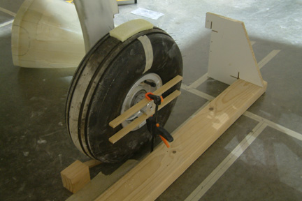 Before
any cutting and sanding, I added a couple simple alignment aides: Before
any cutting and sanding, I added a couple simple alignment aides:
- I cut 2 strips of soft flexible foam strips (yellow)
approximately 3 x 1 1/2 x 3/8" and 5 min. epoxied them onto the top of both
wheels. This allows me to 'rest' the pants on top of the wheels while assuring
3/8" spacing above the tires;
- I cut 2 straight strips of wood spacer and clamped them
onto the anchor bolts for guiding the wheel pants. This assures the 9/16"
spacing between the side of the tires and pants. Prior to clamping the wood
strips, I tightened the anchor nuts such that two of the nut faces (sides) are
horizontally level at
0 degrees;
- I also slipped a piece of thick paper (not shown) under the
front of the tire and traced out its outline profile. I transferred this
template/profile onto the underside of the pants for shaping the tire opening
hole;
- Note the small wood block in front of the tire. Its
1.625" tall and is used for keeping the pants up to level;
- The rotisserie is placed along the planned center-line of
wheel pants.
|
|
Trimming and Fitting... |
|
 After
hours of cutting, trimming, fitting, removing, cutting, trimming...the
pants finally fit in place snuggly - with some over sized holes After
hours of cutting, trimming, fitting, removing, cutting, trimming...the
pants finally fit in place snuggly - with some over sized holes . I will
need more clearance around the bottom edges. However, I will wait until I anchor the pants in place
before final trimming for all necessary clearances. . I will
need more clearance around the bottom edges. However, I will wait until I anchor the pants in place
before final trimming for all necessary clearances.
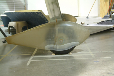
If you look close, you can see the yellow foam above the axle nut and that the pre-marked crosshair (from Sam James) is lined up
exactly over the center of the anchor nut (i.e. the tallest point of the wheel
pant is over the highest point of the tires).
|
|
 I
repeated the laser / digital level alignment (as above) to make sure the pants
are level to the ground. Recall, my
fuselage is set at 2o nose high at this time. Therefore, when I am
done, the wheel pants will be 2o nose down relative to fuselage
level. The digital level is there to validate my horizontal laser line. I
repeated the laser / digital level alignment (as above) to make sure the pants
are level to the ground. Recall, my
fuselage is set at 2o nose high at this time. Therefore, when I am
done, the wheel pants will be 2o nose down relative to fuselage
level. The digital level is there to validate my horizontal laser line.
|
|
Inboard Attachment Point (1st & 2nd Trials) |
|
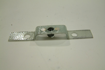
 I
made a small sheet metal bracket (1/2" tall) that spans between 2 of the axle
bolts. Then I riveted a nut plate at mid-point for the inboard attachment point.
The 1/2" dimension was derived from a couple Cozy builders' memory. I
made a small sheet metal bracket (1/2" tall) that spans between 2 of the axle
bolts. Then I riveted a nut plate at mid-point for the inboard attachment point.
The 1/2" dimension was derived from a couple Cozy builders' memory.
If you recall my wheel pant dimensions (above) are 8.5" wide.
The wheel width is 7.5" between the inboard and outboard
tire surfaces. Since I used up 9/16" using the Van's axle nut, 1/2" clearance at
the inboard
attachment point made it perfect...Not quite!
After I attached the pants on these two points, I was able
to see that there is no way I can trim the pants to get 1/4" clearance at the
outboard surfaces of the tire .
It is because of the slight inward curvature of the pants right at the tire. If I want to
keep these wheel pants, I must move the entire pant outboard. In other words, I
have to minimize the inboard bracket height or get rid of the bracket all
together and find a different way of attaching the inboard
side of the pants !@#$%, !@#$%, !@#$%... .
It is because of the slight inward curvature of the pants right at the tire. If I want to
keep these wheel pants, I must move the entire pant outboard. In other words, I
have to minimize the inboard bracket height or get rid of the bracket all
together and find a different way of attaching the inboard
side of the pants !@#$%, !@#$%, !@#$%...
|
|
 I
re-calculated the minimum height for the inboard bracket to be 3/8" (height of
nut + 2 threads + 1/16" thickness of sheet metal). Making a sheet metal bracket with tight bends (multiple
1/4" at 90o with consistency) was getting difficult. I decided to make
it out of 5-ply BID instead. To replace the bracket, I must first remove
the tire to get to the bolt head. To get to the bolt head, I must remove the
tire. To remove the tire, I must jack up the plane. Once I jack up the main
gear and put it back down, I will lose the center line of the plane (on the ground)
for aligning the wheel pants. That means I have to re-draw the center line of
the plane again...Grrr. The 5-ply BID turned out to be a bit too flimsy and I
just realized this whole assembly may get pretty hot. A fiber glass bracket may
not be a good idea. Now I know why other Cozy builders were complaining. I
re-calculated the minimum height for the inboard bracket to be 3/8" (height of
nut + 2 threads + 1/16" thickness of sheet metal). Making a sheet metal bracket with tight bends (multiple
1/4" at 90o with consistency) was getting difficult. I decided to make
it out of 5-ply BID instead. To replace the bracket, I must first remove
the tire to get to the bolt head. To get to the bolt head, I must remove the
tire. To remove the tire, I must jack up the plane. Once I jack up the main
gear and put it back down, I will lose the center line of the plane (on the ground)
for aligning the wheel pants. That means I have to re-draw the center line of
the plane again...Grrr. The 5-ply BID turned out to be a bit too flimsy and I
just realized this whole assembly may get pretty hot. A fiber glass bracket may
not be a good idea. Now I know why other Cozy builders were complaining.
|
Inboard Attachment Point (Alternative
Thought)
My first trial uses ~3/8" minimum clearance, there is no
more room to squeeze out - unless I allow the bolt ends to stick out past the
inboard face of the wheel pants. Obviously, I have to make a small cover (bump)
for those protruding bolts - Sigh... I checked with other 'successful' Sam James
pants people and found out 'Buly' had to do so as well. Hmmm...
|
Inboard Attachment Point (3rd Trial) |
|
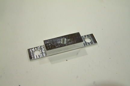 My
last trial (with the inboard bracket approach) was to mill the
'bracket' out of a small piece of aluminum. Instead of a nut plate, I drilled
& tapped a 1/4 x 28 hole at the center to accommodate the mounting bolt. Making the part
was much easier than expected and I can certainly control the height dimension
accurately. It turned out well. My
last trial (with the inboard bracket approach) was to mill the
'bracket' out of a small piece of aluminum. Instead of a nut plate, I drilled
& tapped a 1/4 x 28 hole at the center to accommodate the mounting bolt. Making the part
was much easier than expected and I can certainly control the height dimension
accurately. It turned out well.
Again, I have to remove the tires etc. etc. to replace the
fiber glass bracket with this one. I also ground down all the 4 bolts to a
minimum 2 threads past the nuts.
|
|
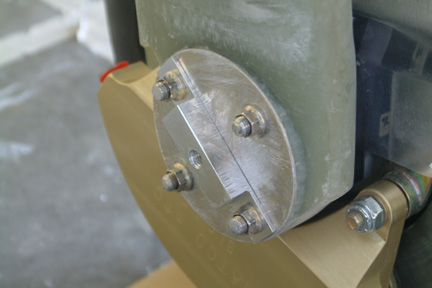 This new 'bracket' works out well. It sat flush on the
inboard axle plate and is held down by 2 of the 4 axle nuts. This new 'bracket' works out well. It sat flush on the
inboard axle plate and is held down by 2 of the 4 axle nuts.
|
|
Additional Spacers at the Axle
Nut Locations |
|
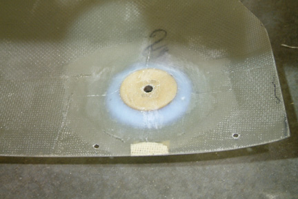 Using minimum spacing at the inboard side, I
was able to squeeze a bit more clearance at the outboard side. That means I need
an additional spacer to fill the gap. I used a 1 1/2" hole saw
and cut up 2 high density 1/4" thick wood discs (with 1/4" center hole) as
a spacer. I lined up the 1/4" center hole to the pants, added a flox fillet around
the discs and glassed it onto the pants with a 2-ply BID. Between Van's axle nut
(9/16") and the 1/4" spacer, I should get ~3/4" clearance between the tire and
pant surfaces (supposedly). Using minimum spacing at the inboard side, I
was able to squeeze a bit more clearance at the outboard side. That means I need
an additional spacer to fill the gap. I used a 1 1/2" hole saw
and cut up 2 high density 1/4" thick wood discs (with 1/4" center hole) as
a spacer. I lined up the 1/4" center hole to the pants, added a flox fillet around
the discs and glassed it onto the pants with a 2-ply BID. Between Van's axle nut
(9/16") and the 1/4" spacer, I should get ~3/4" clearance between the tire and
pant surfaces (supposedly).
The function of the inboard and outboard bolts is to
keep the pants pointing in the desired direction - in this case, parallel to the
center line of the fuselage. The rotisserie came in real handy for this
function. I will use the fairings to maintain the nose
up/down position.
|
|
Patching Up |
|
 Once
I bolted the wheel pants in place with both inboard and outboard axle bolts, I
got a much better idea of the pants mounting positions. I can certainly see the
extra large cut outs I made during the cutting and fitting process at the main
gear Once
I bolted the wheel pants in place with both inboard and outboard axle bolts, I
got a much better idea of the pants mounting positions. I can certainly see the
extra large cut outs I made during the cutting and fitting process at the main
gear  ...Its
time to patch them back up. Concurrently, I was planning to anchor the pants to
the fairings, I decided to beef up the wheel pants at those locations anyway. I made a couple
cardboard templates, added packing tape to its underside and taped them over
the openings with masking tape. The cardboard was just stiff enough to
hold its curved shape. I laid 4-ply BID (4" x 5") at those locations. ...Its
time to patch them back up. Concurrently, I was planning to anchor the pants to
the fairings, I decided to beef up the wheel pants at those locations anyway. I made a couple
cardboard templates, added packing tape to its underside and taped them over
the openings with masking tape. The cardboard was just stiff enough to
hold its curved shape. I laid 4-ply BID (4" x 5") at those locations.
|
|
Fairings |
|
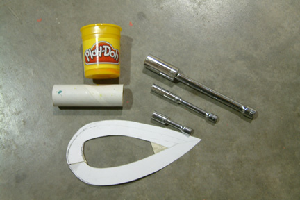 Transition
fairings between the main gear legs and the wheel pants were the next step. One
of the key functions of the fairing is to maintain the pants in its intended
nose up/down position at all times. I
used the same Play Doh (K-Mart special) approach to establish the forms for the
fairings. First, I used the carpenter's widget to establish the curvatures of
the gear legs. Then I transferred these curvatures onto a card board and added
1" width all around. Using these templates, I traced out their outline onto the
wheel pants. The tools I used to form the fairing shapes include the Play Doh,
template (above), paper roller covered with packing tape, and different sizes of
sockets with extensions. Transition
fairings between the main gear legs and the wheel pants were the next step. One
of the key functions of the fairing is to maintain the pants in its intended
nose up/down position at all times. I
used the same Play Doh (K-Mart special) approach to establish the forms for the
fairings. First, I used the carpenter's widget to establish the curvatures of
the gear legs. Then I transferred these curvatures onto a card board and added
1" width all around. Using these templates, I traced out their outline onto the
wheel pants. The tools I used to form the fairing shapes include the Play Doh,
template (above), paper roller covered with packing tape, and different sizes of
sockets with extensions.
|
|
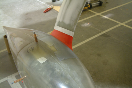 Here's
a picture of the fairing form with red Play Doh. Later I taped up the Play Doh
with electrical tape such that they can be dug out (removed) easier after the
glass cures. Here's
a picture of the fairing form with red Play Doh. Later I taped up the Play Doh
with electrical tape such that they can be dug out (removed) easier after the
glass cures.
I have to sand off some of the finishing micro (Chapter
25) that I jumped ahead a few months prior, such that I'll have a good glass to
glass bond.
|
|
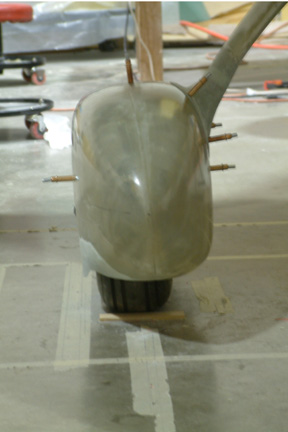
 Here's
a picture of my fairing with 6-ply BID and peel-plied. I used 6-ply BID for 2 reasons: Here's
a picture of my fairing with 6-ply BID and peel-plied. I used 6-ply BID for 2 reasons:
- the fairings must be stiff enough to keep the pants from
tipping (nose up/down);
- the thickness of the fairing needs to be ~0.078" to
accommodate the thickness of the counter washers as recommended by the Plan.
Notice the trailing edge of the fairings following the gear leg curvature?
|
|
Securing the Pants to the Fairings |
|
 After
the glass cured, I spent several hours of 'quality time' digging out the Play
Doh and electrical tape out of the fairing cavities - doing it upside down and
around the tire to boot! I had a wonderful time...not! After
the glass cured, I spent several hours of 'quality time' digging out the Play
Doh and electrical tape out of the fairing cavities - doing it upside down and
around the tire to boot! I had a wonderful time...not!
Here's a picture showing the pants clecoed in place. I
am pleased to learn that the pants are secured, even with just 4 clecos!
|
|
Final Trimming |
|
 At
this time, my wheel pants are secured by the axle bolts (left/right) direction
and the fairing (up/down) position. The remaining task is to final trim around
the wheel openings to assure the necessary clearance. There were many
discussions in the Forum regarding clearances, I decided to go with 1/2"
clearance all around. It was clear that I will not have any problem with the
1/2" (pants to tire) clearance at the fore, aft and inboard sides. The outboard
edge was a different story... Due to the 'curving in' of the lower pant walls,
they have to be trimmed back and up, thus, exposing more tire surface.
Nonetheless, I eventually got the 1/2" clearance all around, except at the fore
and aft corners of the tire, I got 3/8" at those locations.. At
this time, my wheel pants are secured by the axle bolts (left/right) direction
and the fairing (up/down) position. The remaining task is to final trim around
the wheel openings to assure the necessary clearance. There were many
discussions in the Forum regarding clearances, I decided to go with 1/2"
clearance all around. It was clear that I will not have any problem with the
1/2" (pants to tire) clearance at the fore, aft and inboard sides. The outboard
edge was a different story... Due to the 'curving in' of the lower pant walls,
they have to be trimmed back and up, thus, exposing more tire surface.
Nonetheless, I eventually got the 1/2" clearance all around, except at the fore
and aft corners of the tire, I got 3/8" at those locations..
|
|
 Here's
a picture of the inboard side of the wheel pants. You can also see a different
view of the completed fairings. Here's
a picture of the inboard side of the wheel pants. You can also see a different
view of the completed fairings.
I do not know the efficiency of the pants in relationship
to the amount of exposed tire. I just did not like the 'extra' cut outs and
decided to cover them up a bit. All I have to do is to 'extend' the current
edges straight down vertically, thus retaining the same clearance.
|
|
Side Wall Extension Using Pour Foam
Approach |
|
 I
made a dam wall with cardboard and mixed up some pour (liquid) foam along the
outboard side of the right pant. Once cured, I sanded it down to a pleasing
shape. My intention was to lay 1-ply BID on the foam to establish the new shape of
the 'extended' outboard wall, then, remove the inner foam and add 2-3 ply BID on the
inside. I
made a dam wall with cardboard and mixed up some pour (liquid) foam along the
outboard side of the right pant. Once cured, I sanded it down to a pleasing
shape. My intention was to lay 1-ply BID on the foam to establish the new shape of
the 'extended' outboard wall, then, remove the inner foam and add 2-3 ply BID on the
inside.
|
|

Here's a picture after the pour foam is shaped. It took me
a couple hours to get it to a pleasing shape. The problem with this approach is
that I lost visibility of the cut line and the eventual thickness of the side
walls. I have to carve it by 'visual queue' instead of some dimensional guide.
|
|
 After
the glass cured, I dug out the foam and re-trimmed the new outboard wall for the
1/2" clearance. You can see the original cut line and the new cut line. Though
it looks less significant in the pictures, it turned out much better - there is
a lot less exposed tire surfaces and... After
the glass cured, I dug out the foam and re-trimmed the new outboard wall for the
1/2" clearance. You can see the original cut line and the new cut line. Though
it looks less significant in the pictures, it turned out much better - there is
a lot less exposed tire surfaces and...
|
|
the front view is much better than before as well.
|
|
Side Wall Extension Using Play Doh
Approach |
|
 I
decided to take a different approach with the left wheel pants. I cut up 1/2"
strips of the yellow soft foam (above) and glued them along the outboard face of
the tire. Then I used Play Doh (K-Mart) to fill the gap between the soft foam
and shaped them (with rollers) - level with the yellow foam. I taped them up
with electrical tape and laid 1-ply BID over the entire area. I
decided to take a different approach with the left wheel pants. I cut up 1/2"
strips of the yellow soft foam (above) and glued them along the outboard face of
the tire. Then I used Play Doh (K-Mart) to fill the gap between the soft foam
and shaped them (with rollers) - level with the yellow foam. I taped them up
with electrical tape and laid 1-ply BID over the entire area.
I was able to apply the Play Doh with the pants mounted in
place. This way, I can make a continuous line, joining the forward cutout to the
aft.
|
|
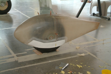
 Here's
a picture of the left pant after the Play Doh is removed with initial trim. I
trimmed to 1/2" clearance all around, except at the fore and aft tire corners
where I have a 3/8" clearance. This time, there is enough room for me to add more
clearance, but I like to keep the pant skirts lower than before. Again, you can
see the prior cut line showing behind the 1-ply BID. My next step is to add
a 5-ply BID to stiffen up the skirts. Here's
a picture of the left pant after the Play Doh is removed with initial trim. I
trimmed to 1/2" clearance all around, except at the fore and aft tire corners
where I have a 3/8" clearance. This time, there is enough room for me to add more
clearance, but I like to keep the pant skirts lower than before. Again, you can
see the prior cut line showing behind the 1-ply BID. My next step is to add
a 5-ply BID to stiffen up the skirts.
|
Nut Plates
After the 5-ply BID were added from inside, I replaced the clecos with nut plates. I floxed the nut plates in place an glassed over them
with 2-ply BID. The 5-ply BID stiffens the side walls quite a bit and they do not
flex much at all.
|
Pre-Fill |
|
 After
the nut plates are secured, I decided to pre-fill the seam where I added the 5-ply BID skirt. I also pre-filled the joint between the 2 halves of the pants. The
mating seam of my pants (front & back) does not fit well at all - therefore, a
pre-fill is necessary. Notice the extended skirt covered up most of the exposed
tire (above). After
the nut plates are secured, I decided to pre-fill the seam where I added the 5-ply BID skirt. I also pre-filled the joint between the 2 halves of the pants. The
mating seam of my pants (front & back) does not fit well at all - therefore, a
pre-fill is necessary. Notice the extended skirt covered up most of the exposed
tire (above).
I will perform the final fill when I return to Chapter 25
for the rest of the plane.
|