Chapter
16 - Section 4
Installation
of Pitch & Roll Assembly
Attaching
the Bearing Blocks (CS109 & CS18)
I
did not have my fuselage laying on its side when attaching the bearing blocks.
Therefore, holding up the blocks while it was being cured was somewhat of a
challenge, especially since the plan recommends to keep the torque tube assembly in
tact to assure perfect alignment. I hot glued a small support fixture at the
bottom of the blocks (per plan), applied duct tape to keep the top of the block
in place and added a little 5 minute epoxy with the flox at the top and
bottom edges of the bearing block. Unfortunately, I was not able to hold the
block in place against the weight of the torque tube. The plan recommends using
nails through the fuselage walls but I am always reluctant to put holes through a
nice surface I tried so hard to achieve prior.
|
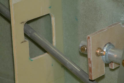
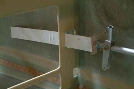 My
father-in-law happened to be in town looking over my shoulder while I was struggling over
this attachment effort. He went over to my scrap wood pile and broke off a
small piece of 2" wide board and wedged the bearing block in place
(left). To my
surprise, it worked great! No fixtures to make, no holes, no 5 minute epoxy... My
father-in-law happened to be in town looking over my shoulder while I was struggling over
this attachment effort. He went over to my scrap wood pile and broke off a
small piece of 2" wide board and wedged the bearing block in place
(left). To my
surprise, it worked great! No fixtures to make, no holes, no 5 minute epoxy... . .
I
repeated the same idea to the rear bearing blocks by cutting a piece of board
(similar to the one shown) and wedged the bearing block against the seat back
support wall. Once
cured, I radiused the inside corners with flox and glassed over the bearing blocks
with 2 ply BID on both sides. I then trimmed off the edges and holes after cure
per plan.
|
Setting
Torque Tube Positions
Before
drilling the torque tube holes for CS121 to CS122 (the bolt that connects the
control stick angle to the aileron position), I used the following methods to
set their positions, but first, I made sure the fuselage was level:
|
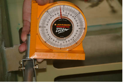 For the Control Stick
(10o tilt inboard), I used a dial level and butted it against the
control stick. Rotate the stick until I got 10o and left it alone. I
repeated the same on the other side. For the Control Stick
(10o tilt inboard), I used a dial level and butted it against the
control stick. Rotate the stick until I got 10o and left it alone. I
repeated the same on the other side.
|
|
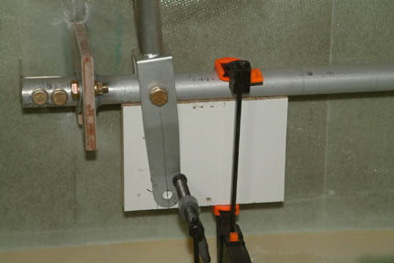
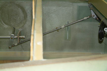
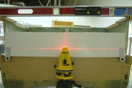 I
butted a self leveling laser against the center of the firewall which, at the
same time, casts a horizontal line outwards. I rotated the aileron 'ears' (CS124)
until the two holes are lined up to the horizontal laser beam. That establishes my straight and level
torque tube position. I
butted a self leveling laser against the center of the firewall which, at the
same time, casts a horizontal line outwards. I rotated the aileron 'ears' (CS124)
until the two holes are lined up to the horizontal laser beam. That establishes my straight and level
torque tube position.
There
is no clear specification in the written plans as to the distance between the aileron
control ears and the firewall, other than "the heads of the bolts attaching
the rod ends will not strike the firewall...". However, I found that distance from
M-9 drawing and determined it to be
~3/4". So, I placed a
3/4" board against the firewall and bent the aileron 'ears' until they were flat
against the board.
|
|
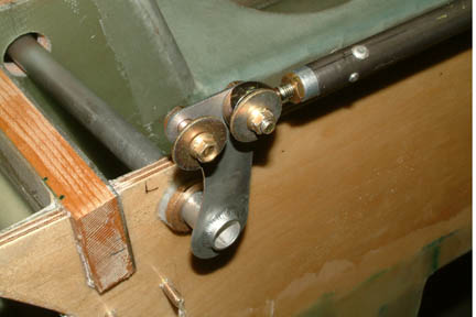
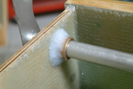 Once
the positions of the torque tubes were established (above), I match-drilled both
(CS121 & 122) torque tubes with my drill-press, re-assembled and tightened all the bolts (per
plan direction) making sure that the torque tubes rotate smoothly. I then floxed the bushing (CS123) in place. After
cure, I double checked for
smooth rotation of torque tubes +/- 20 degrees with no slop - they were Once
the positions of the torque tubes were established (above), I match-drilled both
(CS121 & 122) torque tubes with my drill-press, re-assembled and tightened all the bolts (per
plan direction) making sure that the torque tubes rotate smoothly. I then floxed the bushing (CS123) in place. After
cure, I double checked for
smooth rotation of torque tubes +/- 20 degrees with no slop - they were !
Matter of fact, I have to rotate the control stick ~40 degrees before the bottom of the fork touches the fuselage wall, therefore,
no trimming on the fuselage side was necessary. !
Matter of fact, I have to rotate the control stick ~40 degrees before the bottom of the fork touches the fuselage wall, therefore,
no trimming on the fuselage side was necessary.
|
|
 Once
completed, I made the aileron linkage rod (CS125) and connected it to the two
aileron 'ears'. Once connected, the two control sticks move in sync - like my
wind shield wipers! Since I used MM4 eye bolts (instead of MM3 per plan change),
the matching AN970-4 washers were too big and would interfere with its
neighboring washer. Therefore, I used two AN970-3 instead - but I have to open
up the bolt holes to accommodate the AN4 bolt. Once
completed, I made the aileron linkage rod (CS125) and connected it to the two
aileron 'ears'. Once connected, the two control sticks move in sync - like my
wind shield wipers! Since I used MM4 eye bolts (instead of MM3 per plan change),
the matching AN970-4 washers were too big and would interfere with its
neighboring washer. Therefore, I used two AN970-3 instead - but I have to open
up the bolt holes to accommodate the AN4 bolt.
|
Elevator
Push Rods
To
mount the elevator push rods, I need to set the the control stick with 5o
forward cant while the elevators are at neutral (0o) position. I followed
Wayne Hicks approach for setting these positions:
|
 5o
forward cant... 5o
forward cant...
|
|
 and
elevators at neutral (0o) position. The
elevator angles on the fuselage were leftover markings from Chapter 12 (Mounting
the Canard) per the alignment jig. and
elevators at neutral (0o) position. The
elevator angles on the fuselage were leftover markings from Chapter 12 (Mounting
the Canard) per the alignment jig.
|
I
measured the distance from elevator and control stick attachment points (i.e.
center of bolt holes) and my distance came to 24.1". Here's how my
dimensions came together:
Eye bolt to insert ends @ 0.875x2 = 1.75"
CS1A insert protruded outside CS102 tube @ 0.25x2 = 0.500"
CS102
= 14.0"
CS136
= 7.85" (0.85" longer than plan)
Total
length
= 24.1"
|
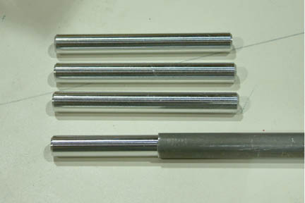 I
had a tough time locating the CA181 disconnect insert. Aircraft Spruce, Wicks
nor the Cozy Girrrls carry them at this time. I finally got my 2024T3 tubing
from McMaster-Carr and had Jamie turn the OD down with a lathe. As always, Jamie
made the 4 inserts with superb quality (though I only needed 2). Actually, he felt
the plan tolerance was too sloppy and made mine with .429" OD instead. In
addition, he tapered the insert ends as well. You
couldn't find a better fit... I
had a tough time locating the CA181 disconnect insert. Aircraft Spruce, Wicks
nor the Cozy Girrrls carry them at this time. I finally got my 2024T3 tubing
from McMaster-Carr and had Jamie turn the OD down with a lathe. As always, Jamie
made the 4 inserts with superb quality (though I only needed 2). Actually, he felt
the plan tolerance was too sloppy and made mine with .429" OD instead. In
addition, he tapered the insert ends as well. You
couldn't find a better fit...
|
|
 I
installed the eye bolts on each end of CS102 and CS136 using the rivets per plan.
I proceeded to drill out the rivet holes for the disconnect inserts (CS181) - not
paying close attention, I ended up putting the rivets on CS136 instead. I do not
expect it'll be much of a problem, I just have to make both sides match. I
installed the eye bolts on each end of CS102 and CS136 using the rivets per plan.
I proceeded to drill out the rivet holes for the disconnect inserts (CS181) - not
paying close attention, I ended up putting the rivets on CS136 instead. I do not
expect it'll be much of a problem, I just have to make both sides match.
I
did not use the clevis pin as a quick disconnect. I followed most of the
builders and used an AN3 bolt to eliminate any slop in the push rods. I decided
to use an AN3-7 bolt which has a pre-drilled hole at the tip such that I can put
a safety key through it, just an added precaution. Note the masking tape holding
the rivets in place during trial fit.
|
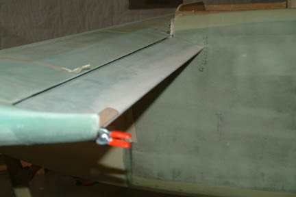
Trimming
Push Rod Clearance at F22
 Similar
to many Cozy builders, my push rod hole at the Instrument Panel was not large enough to
accommodate the -20o movement. I took some measurements and determined
that 0.4" of additional clearance is needed. Once trimmed and rounded off
its corners, I was able to get a maximum of +/- 25o of freedom at the
control stick. Similar
to many Cozy builders, my push rod hole at the Instrument Panel was not large enough to
accommodate the -20o movement. I took some measurements and determined
that 0.4" of additional clearance is needed. Once trimmed and rounded off
its corners, I was able to get a maximum of +/- 25o of freedom at the
control stick.
|
Aileron
Pushrods
This
was performed in Chapter 19 Section 11.