The
plan's pitch trim system design is similar to the roll trim design - except its
a bit simpler. What I gathered from the Cozy archives is that the pitch trim
gets used quite often in flight and that an electric trim is a nice convenience.
I looked at the Davenport System and Alex Strong's System and I decided to get
the Strong System. The Strong System is mounted on the side of the fuselage
while the Davenport System mounts at the center (behind the Instrument Panel) -
thus taking up valuable space for potential shelving for electronic instruments
down the road. In addition, the Strong System looks like less work for me - I
do not have to build the leaf spring, match up an actuator (though I already
found one), and build the CZPT-1 etc. I think the lazy bug must have gotten the better part of
me that day![]() !
!
I read and heard about the sticking problem with the Strong System if they run the motor (shaft) all the way to the end. I discussed this with Alex Strong and learned that he has added a couple of limit switches to 'limit' the travel envelop, thus eliminating the sticking problem. I am comfortable with this solution because I have worked with limit switches in the past in motion control applications and they are pretty reliable... When installed correctly, they can stop servo or stepper motors (with much larger mass and momentum) dead in its tracks in milliseconds...
I also checked with Trio Avionics (Auto Pilot System) regarding their Altitude Hold / Automatic Trim Adjust capability and found that it is compatible with the Strong's stepper motor. That's nice, because their Altitude Hold will adjust Strong's electric trim system in parallel. Therefore, if I ever disengage the Altitude Hold (auto-pilot), the electric trim would have been set already at the appropriate envelop for 'pilot command steering' mode - no quick jerk motions (supposedly)...
The Strong System arrived 4 days after I mailed the check out (we are both in CA and about 150 miles apart). That was nice because I was ready for the pitch trim step at this time. I unpacked the unit and did a quick visual check on all the parts. I have to admit that I was a bit disappointed with the appearance of the parts - though they may be perfectly functional. Regardless, I can live with the appearance issue as long as the pitch trim is working as good as advertised...
The first thing I did was read through ALL the documentation that came with the system - it was rather easy to understand. Then I hooked up the pitch trim system wiring and mounting per instructions (I ordered the PWM relay and the reversing relay because I was planning to control it with the HAT switch on my control stick). I used a bench power supply to drive the unit because I can monitor the output power (12VDC) and the current draw (~1 amp) while the pitch trim motor is activated. I hooked a voltmeter across the PWM (per instruction) for setting the 'speed control' pot. I also hooked up a SPST switch in each direction (Radio Shack) to activate the motor in the up and down direction.
The pitch trim motor rotates promptly once power was applied. I exercised the motor back and forth a few times (all within the limit switches), just to get a feel for the system's responses. The motor and the pitch screw was a bit wobbly - normally its an indication of the pitch screw being not perfectly straight. Regardless, I decided to take the big step and drove the operator (i.e. copper arm) to its full retract limit switch position. Whatever the reason was, the limit switch did not stop the operator and the lead screw housing went all the way to the end of the lead screw and stuck in the retract position - that's not good I thought...
I decided to call Alex Strong for help. We eventually tracked down the cause - the torque setting was sitting at Max (6) while it should be set between 1 and 2. Alex normally sets the motor torque and tapes it down before shipping (except in my case). He also told me the wobble was mostly caused by the motor shaft not being concentric relative to the motor housing. Alex was very patient in explaining the workings of his pitch trim system (such as the function of the trim pot, etc.). I reset the torque and pot afterwards and ran the pitch trim system again - back and forth all the way to both limit switches with no more sticking problem...
My next step was to mount the pitch trim onto the appropriate torque tube. I rechecked the neutral elevator position and the stick at 5o forward. I had to open up the hole at the Instrument Panel a bit (~1" lower) to accommodate the pitch screw housing - that was no problem. I used a laser to establish the height of the mounting bracket (~11" max from the fuselage floor) per instructions.
|
[Hindsight] I eventually had to rotate the 'U' clamp a bit for better alignment and fit. If I had put the roll pin in, I'd be stuck. I highly recommend to wait until you have tested out the pitch trim system completely before drilling the hole, if at all.
|
|
I did not glass the mounting bracket against the fuselage right away per instruction. I wanted to test out everything before making that irreversible commitment. I used a couple of screws and hot glued the mounting plate in place for testing.
|
Once I got the pitch trim assembly hooked up to my elevator torque tube (per instructions), I ran the elevator up and down slowly while keeping a close eye on the mechanical stops of the elevator. The plan elevator travel requirement is 15o up and 30o down - my elevator has 17o up and 32o down - in other words, I have more travel than needed per plan. As I inched up/down to both the elevator stops, I noticed that I still have quite a bit of spacing left before reaching the limit switch. Per my measurement at the limit switch plate, I need ~1 7/8" of travel for full elevator travel (i.e. -17o to +32o), the spacing between the limit switches is 2 1/2". That means I'll hit the mechanical stops of the elevator before touching the limit switch.
I called Alex again and he pointed out that even if I hit the mechanical stop, the motor will continue to move ahead. It will compress the internal springs (inside the pitch screw housing) until it hits the limit switch. He assures me that it will not hurt anything and I that should not worry about it. Hmmmm... I am just not comfortable with stressing against the mechanical stop with the pitch trim motor. I prefer to set the limit switch to stop the motor BEFORE reaching the elevator mechanical stop. Unfortunately, the limit switches are fixed on its mounting plate and no adjustment can be made. I considered modifying the plate for my purpose...
There are many ways to modify the Strong limit switch plate to accommodate my needs. I chose to take the simplest approach FIRST to see how the system works. I removed the limit switch plate from the motor (which was held by a hose clamp) and removed the limit switches. The limit switches were held down to the plate by two (2) miniature bolts and nuts.
|
I re-installed the limit switch assembly to the motor and clamped it down with the hose clamp as before. By activating the motor, I moved my elevator to its max 'down' position (right at its mechanical stop or +32o in my case), SLOWLY and CAREFULLY. I loosened the clamp (that grips the 'operator' onto the pitch screw housing) and slid it forward, until it pushed and closed the 'retract' limit switch. Then I re-clamped it back down with the same hose clamp. I ran the motor back and forth several times to make sure the 'operator' now engages the limit switch right at my max elevator down travel. It did...
I repeated the above procedure for the elevator 'up' position. Again, with the motor, I moved the elevator to the max up position (-17o) carefully. This time I loosened and slid the 'extend' limit switch forward until it butted against the 'operator' and closed. Remember I put a slot on the switch plate (above) for this? Then I re-tightened the miniature bolts and nuts at its new location. Again, I ran the motor back and forth several times to make sure the 'operator' now engages the limit switch right at my max elevator up travel. It did... |
|
I floxed in the mounting bracket per instruction.
|
While I was feeling accomplished, I got a chance to talk to Keith Spreuer (a long time Cozy builder and flyer) on my installation. He thought I should leave the limit switches the way they were; I was truly puzzled. He further explained that once the elevator hits the hard stop (but before the motor hits the limit switch), the motor will continue to push forward - thus compressing the internal spring at the pitch screw. This added compression is beneficial in that it will provide stronger resistance to the wind force at max up and down elevator positions. The extra compression should not hurt the elevator either.
Well,
back to square one. I was glad that I marked down everything before I took the
limit switch plate and 'operator' off. I was able to put it all back the way
it was. Now my pitch trim moves up and down with a 1/4" compression at both
up and down limits. I'll say it for Alex - "I told you so..."![]()
With
all the phone calls and odd questions I posed to Alex, I think he probably
wanted to reach out and smack me one...but he is a patient man![]() .
Thank you Alex!
.
Thank you Alex!
Modifying the Limit Switch Plate and 'Operator'
|
|
|
|
[Hindsight] The motor bracket snaps onto the motor housing real well. Since it will not be seeing any pressure against it, just a bit of flox or glass should keep it in position for good.
|
|
|
|
With some estimation and trimming, the trigger lever is completed. Note the trigger lever is pie shaped to accommodate the back lash motion of the pitch screw. Though the back lash angle is small (~30o), I used 90o, just in case I needed it later on...
|
Final Assembly and Test
This
modification relocated the limit switches closer to the trigger lever, but they
are fixed in position (via the rigid strip). The only moving part is the trigger
lever, which is secured onto the pitch screw housing. These two parts do not
touch or rub against each other except when it triggers the limit switches at
the end of the travel. The contact force is light - not enough to bump each
other out of position. The
modification works nicely throughout my initial tests (both on the bench and on the
elevator). There is no binding or missing of the limit switches. with this mod,
I can set the pitch trim travel to my mechanical stops or full travel as
desired. Right now, I have it set at maximum travel. So far so good |
| From Position | To Position | Elapsed Time |
| Neutral | Max. Up (-17o + 1/4" of pitch travel) | 8 seconds |
| Neutral | Max. Down (+32o + 1/4" of pitch travel) | 15 seconds |
| Max. Up | Neutral | 9 seconds |
| Max. Down | Neutral | 21 seconds |
Once completed, I removed all the electronics and kept them in storage until my control stick arrives down the road.
|
[Hindsight] Currently, I
am working on Chapter 23, 24 and 25. However, I had an opportunity to explore a
different pitch trim design (by Vance Atkinson)
Here's a picture with all the parts... - aluminum tube; - two (2) plugs - one long and one short with drill & tap holes and/or through holes; - a 1/4" thick washer; - a 1/4" steel rod threaded on both ends; and - two (2) 6 1/4" springs at any hardware store. |
|
|
|
|
|
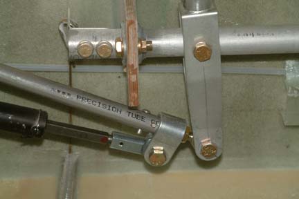
Vance's pitch trim system is several inches longer than Strong's. Therefore, I have to remove the original anchor bracket and re-install a new one. It took me a couple of hours to switch over. The new motor runs really smooth - I like it much better. Anyone want a pre-owned Strong's system?
Here's the picture of the new install. With the higher load (100lbs), the motor moves the elevator with ease. It took just 4 seconds to go full up and full down positions vs 8/9 seconds with the Strong unit. |
|
Here's the picture of 3 BID of glass over the mounting bracket as well as covering up the gouges I made when removing the Strong bracket.
Here's a video showing my modified trim system:
|
 The
instructions called for drilling and inserting a roll pin through the 'U' clamp at the end
of the elevator torque tube. I was a bit hesitant to do so (I am
glad I was) because that will lock up my MM-4 torque end threaded screw. I tried
to tighten the 'U' clamp around the CS102 torque tube instead with no avail. The
circumference of the 'U' clamp was a bit larger the the diameter of the CS102 and
the thickness of the MM-4 at the square shaft prevents me from squeezing the 'U'
clamp any tighter.
The
instructions called for drilling and inserting a roll pin through the 'U' clamp at the end
of the elevator torque tube. I was a bit hesitant to do so (I am
glad I was) because that will lock up my MM-4 torque end threaded screw. I tried
to tighten the 'U' clamp around the CS102 torque tube instead with no avail. The
circumference of the 'U' clamp was a bit larger the the diameter of the CS102 and
the thickness of the MM-4 at the square shaft prevents me from squeezing the 'U'
clamp any tighter.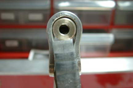 I
called Alex again and posed my problem. He called me back in 15 minutes and
suggested I wrap a .010 thick, "3/4" wide and 180o turn of
shim strip (roof flushing material) around the CS102 torque tube and try again. It
turned out to be a 3/4" x 3/4" x .010" of shim size. I went to Home Depot and
found some, except they sell it by 1' x 10' for $9. I mentioned it to Alex
(jokingly), and he offered to reimburse me for it. That was thoughtful of him but
totally unnecessary. However, I will offer the excess material to whoever needs it -
free of charge of course! The shim worked...
I
called Alex again and posed my problem. He called me back in 15 minutes and
suggested I wrap a .010 thick, "3/4" wide and 180o turn of
shim strip (roof flushing material) around the CS102 torque tube and try again. It
turned out to be a 3/4" x 3/4" x .010" of shim size. I went to Home Depot and
found some, except they sell it by 1' x 10' for $9. I mentioned it to Alex
(jokingly), and he offered to reimburse me for it. That was thoughtful of him but
totally unnecessary. However, I will offer the excess material to whoever needs it -
free of charge of course! The shim worked...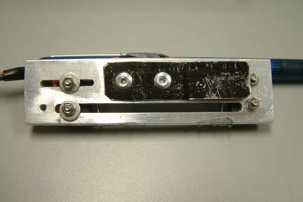 After
a few measurements, I decided to leave the 'retract' limit switch as is (the 2
screws to the right in the picture), but
make the 'extend' limit switch adjustable and move the neutral
point accordingly. I took the plate to a nearby machine shop and extended the
top hole to a 3/4" slot with an end mill. While I was at it, I smoothed out
the 'operator' track with the same end mill as well. That was all the
modification needed.
After
a few measurements, I decided to leave the 'retract' limit switch as is (the 2
screws to the right in the picture), but
make the 'extend' limit switch adjustable and move the neutral
point accordingly. I took the plate to a nearby machine shop and extended the
top hole to a 3/4" slot with an end mill. While I was at it, I smoothed out
the 'operator' track with the same end mill as well. That was all the
modification needed.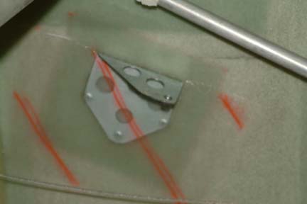 Now,
the Strong System will stop right at the max up (-17o) and max down (+32o)
positions of my elevator. My total pitch screw travel is 2"
(1 3/8" down, 5/8" up) while the Strong travel envelop is 2 1/2"
- more than enough to accommodate
my requirements. This slight mod shortened the distance between the two limit
switches and worked out nicely.
Now,
the Strong System will stop right at the max up (-17o) and max down (+32o)
positions of my elevator. My total pitch screw travel is 2"
(1 3/8" down, 5/8" up) while the Strong travel envelop is 2 1/2"
- more than enough to accommodate
my requirements. This slight mod shortened the distance between the two limit
switches and worked out nicely.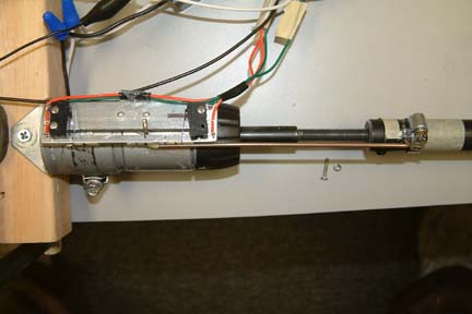 With
all the switching back and forth, I got to understand the Strong system
components and how they work together. The electronics seem to work fine but I
was never comfortable with the design of the limit switch plate and the copper
wire 'operator' that drags along the plate slot and the uneven surface of the
motor housing. Whenever, I change the trim
direction, the backlash on the pitch screw causes the 'operator' to flip-flop
around quite a bit. During my bench test, the copper wire 'operator' missed the
limit switch (~ 3 times), resulting in a stuck motor and a bent copper
wire. I decided to come up with a different structure to trigger the limit
switches and get rid of the limit switch plate and the copper wire 'operator' totally.
With
all the switching back and forth, I got to understand the Strong system
components and how they work together. The electronics seem to work fine but I
was never comfortable with the design of the limit switch plate and the copper
wire 'operator' that drags along the plate slot and the uneven surface of the
motor housing. Whenever, I change the trim
direction, the backlash on the pitch screw causes the 'operator' to flip-flop
around quite a bit. During my bench test, the copper wire 'operator' missed the
limit switch (~ 3 times), resulting in a stuck motor and a bent copper
wire. I decided to come up with a different structure to trigger the limit
switches and get rid of the limit switch plate and the copper wire 'operator' totally.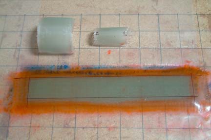 This
new structure consists of 3 fiber glass parts as shown. One is a 16 layer strip of BID which will
be used as a rigid holder for the limit switches. The other 2 circular rings are
6 layers of BID around the motor (motor bracket) and the pitch screw tube (screw
bracket)
respectively. After cure, I trimmed off their rough edges for fabrication.
This
new structure consists of 3 fiber glass parts as shown. One is a 16 layer strip of BID which will
be used as a rigid holder for the limit switches. The other 2 circular rings are
6 layers of BID around the motor (motor bracket) and the pitch screw tube (screw
bracket)
respectively. After cure, I trimmed off their rough edges for fabrication. 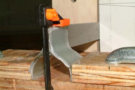 I
rough trimmed the rigid strip to a 1 1/2" x 6" in size. Then I
floxed it onto the apex of the motor bracket with 3 layers of BID on each
side.
I
rough trimmed the rigid strip to a 1 1/2" x 6" in size. Then I
floxed it onto the apex of the motor bracket with 3 layers of BID on each
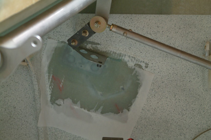
side.  Separately,
I built a trigger lever. I started with 3 layers of BID (2"x2" square)
on a flat surface. Before it cures, I set the screw bracket with its end on top
of the flat BID. Then I floxed the corners and added 3 more layers of BID to the
transition. Picture (at left) shows trigger lever (with weight on top) during
cure. The trigger lever will be trimmed to size later on.
Separately,
I built a trigger lever. I started with 3 layers of BID (2"x2" square)
on a flat surface. Before it cures, I set the screw bracket with its end on top
of the flat BID. Then I floxed the corners and added 3 more layers of BID to the
transition. Picture (at left) shows trigger lever (with weight on top) during
cure. The trigger lever will be trimmed to size later on.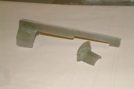 Here's
a picture of the rigid strip after it is trimmed to size and shape. Note the 2
sets of holes for the limit switches. The outer sets are for maximum pitch trim
travel which is the same as the original Strong System. The inner set of holes
are for the pitch trim travel to the mechanical stops of my elevators.
Optionally, I can add another set of holes in between for less stick pressure
AFTER the pitch trim reaches its mechanical stops.
Here's
a picture of the rigid strip after it is trimmed to size and shape. Note the 2
sets of holes for the limit switches. The outer sets are for maximum pitch trim
travel which is the same as the original Strong System. The inner set of holes
are for the pitch trim travel to the mechanical stops of my elevators.
Optionally, I can add another set of holes in between for less stick pressure
AFTER the pitch trim reaches its mechanical stops.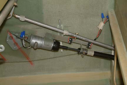 I
re-assembled the limit switches on the rigid strip and snapped it onto the motor
housing. Then I clamped the trigger lever onto the pitch trim housing. I decided
not to flox it in place (at this time) until I completed my actual flight test
down the road. The hose clamp shall hold it in place for now.
I
re-assembled the limit switches on the rigid strip and snapped it onto the motor
housing. Then I clamped the trigger lever onto the pitch trim housing. I decided
not to flox it in place (at this time) until I completed my actual flight test
down the road. The hose clamp shall hold it in place for now.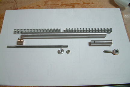 and
I liked it better than the Strong System. The design uses a ball drive actuator
(Motion System PN 85616, 24 volts) which eliminates the limit switches. Once the ball drive reaches
it limits, it will just continue to spin without any adverse effect to the
entire pitch trim system. Vance graciously gave me a copy of his design drawing
to go at it. The pitch trim design was basically very simple, if you have access
to a small lathe, you should be able to make one by yourself. I had a mini-mill
from Harbor Freight and I was able to make all the parts. Precise dimensions are
in the drawing.
and
I liked it better than the Strong System. The design uses a ball drive actuator
(Motion System PN 85616, 24 volts) which eliminates the limit switches. Once the ball drive reaches
it limits, it will just continue to spin without any adverse effect to the
entire pitch trim system. Vance graciously gave me a copy of his design drawing
to go at it. The pitch trim design was basically very simple, if you have access
to a small lathe, you should be able to make one by yourself. I had a mini-mill
from Harbor Freight and I was able to make all the parts. Precise dimensions are
in the drawing.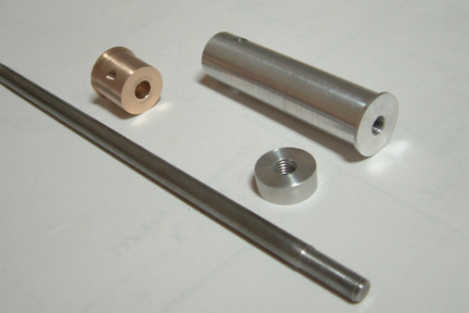 Here's
a closer look at the key parts.
Here's
a closer look at the key parts.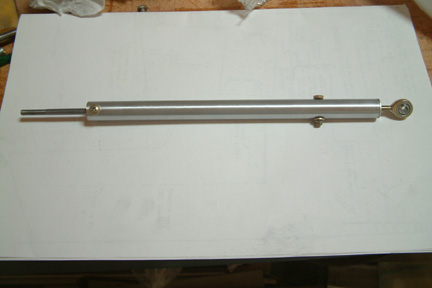 Here's
a pitch trim with all the parts assembled.
Here's
a pitch trim with all the parts assembled.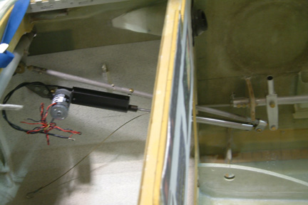 I
also ordered the unit that has a positional pot in it. Here's why. I am planning
to use Vertical Power Electronic Breaker System. Beside the breaker for the
pitch trim, it also has a programming capability that it will reduce its output
voltage at a pre-programmed speed, thus slowing down the travel speed of the
pitch trim at higher airspeed. This reduces the sensitivity at higher airspeed but
retains its sensitivity at lower airspeed such as landing.
I
also ordered the unit that has a positional pot in it. Here's why. I am planning
to use Vertical Power Electronic Breaker System. Beside the breaker for the
pitch trim, it also has a programming capability that it will reduce its output
voltage at a pre-programmed speed, thus slowing down the travel speed of the
pitch trim at higher airspeed. This reduces the sensitivity at higher airspeed but
retains its sensitivity at lower airspeed such as landing.