Chapter
19 - Section 11
Controls
This
section is for building the linkage between the main wings and the control
sticks. Its a short paragraph in the plans, but much work is ahead. I worked on
this section a bit out of sequence because I can make precise measurements to
the linkage hardware, hopefully reducing any slop in my control system. I worked
on this section AFTER I completed Chapter 19, Section 12 and Chapter 14, Section
10.
Marking
the Center of the Torque Hot Wire Hole
 The
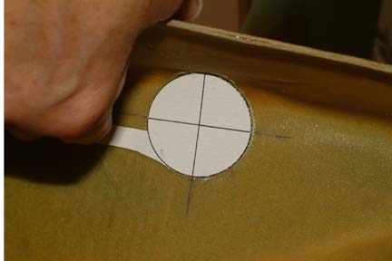
first thing I did was to mark the center of the torque entrance (hot wire hole)
to the main wing / aileron. I drew a 1.6" diameter circle with a cross hair
through its center with my graphics program. I printed it out on semi-thick
paper and cut out the circle with a small handle. Then I placed the circular
template over the 1.6" diameter hot wire hole as shown. The
first thing I did was to mark the center of the torque entrance (hot wire hole)
to the main wing / aileron. I drew a 1.6" diameter circle with a cross hair
through its center with my graphics program. I printed it out on semi-thick
paper and cut out the circle with a small handle. Then I placed the circular
template over the 1.6" diameter hot wire hole as shown.
I
extended the cross hair onto the wing rib surface. These extension marks will be
used to line up my FMN-10 bearing (later) to the center of the torque tube hot
wire hole.
|
Fabricating
the FMN-10 Holder
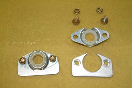
The
plan calls for fabricating a phenolic block to support the torque tube at the
entrance to the main wing and aileron. Many builders recommended using the
FMN-10 bearing as replacement - I decided to follow. However, I need some kind
of mounting widget to hold the FMN-10 in place...
 I
made two (2) holders as shown - one for each wing. I countersunk one side of the
holder such that the screws will be flush to the surface. The bolts I used are
MS24694-95 (they are 1/4-28 instead of the usual 10-32 screws) because the
diameter of the mounting holes for the FMN-10 are 1/4" in diameter. I
made two (2) holders as shown - one for each wing. I countersunk one side of the
holder such that the screws will be flush to the surface. The bolts I used are
MS24694-95 (they are 1/4-28 instead of the usual 10-32 screws) because the
diameter of the mounting holes for the FMN-10 are 1/4" in diameter.
I
hot glued the holder in place throughout the whole trial fit / alignment process.
[Note] I held off
floxing and glassing the holder in place until I completed the entire aileron
control system. Then...
I
ground a flat on each screw head, countersunk the holes and installed with flox.
The next day I tested them by tightening the nuts to it. One held up OK and the
other did not. So I increased the size of the flat and re-floxed in place. This
time it was OK. I also filled the Phillips head with flox when I eventually floxed
the holders to the wings for added resistance to rotation.
Once
the holders were completed, I trial fit the holder in place and traced the
outline of the holder on the wing root. Then I removed everything and applied
wet flox within the holder outline (on the wing root). Then I pressed the holder
against the flox and added a couple drops of 5 minute epoxy to
keep the holder in place.
Once the flox cured, I glassed the entire holder with 3 layers of BID.
I
forgot to take some pictures on the holders when glassing them in place, but you
can make it out (somewhat) from the picture below...
|
Aileron
Torque Tubes
I
added the universal joint and the aileron torque tubes using similar methods as
I did in Chapter 16 Step 2. I started from the aileron end and worked towards
the CS132 (the welded part by Brock). The short tube (CS152) that fit through
CS132 came matched drilled - which made it tougher because the orientation of
the last tube is about an inch inside the torque tube hot wire hole. However,
with the help of a bit of masking tape and careful marking, the problem was solved. I
was able to set the aileron at neutral position and CS132 at 90 degrees.
BTW,
to set CS132 to 90 degrees, I drew a straight line at the face of CS132 joining
the centers of the two holes. Then I used a plumb line as a guide to set its
orientation. It worked fine.
First
Trial
With
the FMN-10 holder hot glued in place, I trial fit the aileron torque tubes. I
got about 12o up and 26o down movements. A quick
investigation revealed that the inboard bolt (of course it had to be the inner
bolt) of the universal joint was rubbing/bumping against the glass inside the
hot wire hole. I had to remove the entire aileron & torque tubes and ground
off some of the glass inside with a Dremel. After some frustrating moments, I
decided to put a dab of grease (that's the only putty stuff I have at that time)
on the head of the bolt to mark the exact rubbing location. Several more times
of removing, sanding and !@#$%, I finally freed the aileron upward movement to
about 23o - good enough!
I
had to repeat the same processes on the left wing. This time the obstruction was
closer to the hole entrance, so there was less removing, sanding and !@#$%...
Mounting
the Belcrank Bearing
I
bought the CS127 brackets (that hold the Belcrank bearing) from the Cozy
Girrrls. They came with all the holes pre-drilled - including the hole for
neutral and 20o positions. That was well worth the money because once
I slipped an AN3 bolt through the neutral hole, the 20o position hole
and mount the Belcrank with an AN4 bolt, I pretty much got the whole assembly
together for fitting.
With
trial and error, I found the optimal assembly position such that the CS129
torque tube will be leveled and 90 degrees to the Belcrank arm. My CS129 turned
out to be 8 1/4" long.
Mounting
the Belcrank Brackets
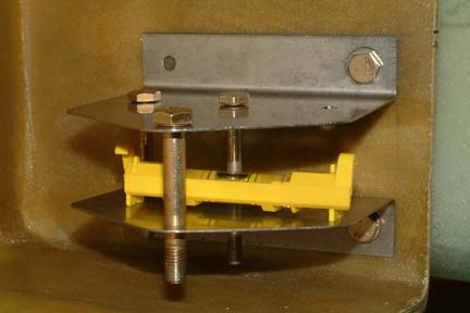 Once
the torque tubes were made and trial fitted, I hot glued the Belcrank
brackets in place. I disassembled the Belcrank assemblies and drilled the
inboard holes first. Then I bolted the bracket in place and removed the hot
glue. I
re-leveled the brackets positions with a miniature bubble level to make sure the
top and bottom brackets are parallel. Note the single bolt through each bracket
as well as the 3 vertical bolts to keep both brackets squared and aligned. Then I marked the second holes and
completed the drilling. Once
the torque tubes were made and trial fitted, I hot glued the Belcrank
brackets in place. I disassembled the Belcrank assemblies and drilled the
inboard holes first. Then I bolted the bracket in place and removed the hot
glue. I
re-leveled the brackets positions with a miniature bubble level to make sure the
top and bottom brackets are parallel. Note the single bolt through each bracket
as well as the 3 vertical bolts to keep both brackets squared and aligned. Then I marked the second holes and
completed the drilling.
|
|
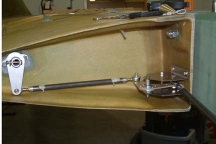 Here's
a picture of my completed Belcrank assemble and aileron torque tubes. Notice I
held down my rivets with masking tape because I want to eventually paint the
torque tubes before squeezing in the rivets permanently. Here's
a picture of my completed Belcrank assemble and aileron torque tubes. Notice I
held down my rivets with masking tape because I want to eventually paint the
torque tubes before squeezing in the rivets permanently.
|
Setting
the Aileron Control Positions
I
was having some difficulty in setting the aileron positions. Somehow, I did
not get the same degree of movement between the ups and the downs... .
I adjusted a bit of this and a bit of that, but was not able to get the 20o
up and 20o down at the same time. I do not have any slop in the control system and I have very minimal resistance or
obstruction in movements. I did not have a clear understanding of the relationship
between the aileron angles and Belcrank movements, I decided to try something a bit more
precise...maybe I can figure out the problem.
.
I adjusted a bit of this and a bit of that, but was not able to get the 20o
up and 20o down at the same time. I do not have any slop in the control system and I have very minimal resistance or
obstruction in movements. I did not have a clear understanding of the relationship
between the aileron angles and Belcrank movements, I decided to try something a bit more
precise...maybe I can figure out the problem.
|
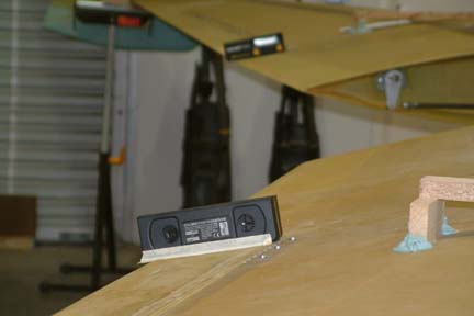 I
mounted a digital level at the inboard edges of both the ailerons as shown. I
set the initial torque tube positions such that both ailerons were at neutral
positions & control sticks at 10o. I recorded the digital level
readings. Then I raised the left aileron up to the hard stop and recorded the
digital level readings again. I repeated the process by reversing the aileron
positions. The readings below were my initial readings with the newly mounted
digital levels: I
mounted a digital level at the inboard edges of both the ailerons as shown. I
set the initial torque tube positions such that both ailerons were at neutral
positions & control sticks at 10o. I recorded the digital level
readings. Then I raised the left aileron up to the hard stop and recorded the
digital level readings again. I repeated the process by reversing the aileron
positions. The readings below were my initial readings with the newly mounted
digital levels:
|
| Aileron Positions |
Left |
Deflection |
Right |
Deflection |
| Neutral |
-12.4 |
NA |
-12.4 |
NA |
| Left up / Right down |
+7.6 |
20.0 |
-33.6 |
21.2 |
| Left down / Right up |
-36.5 |
24.1 |
+9.4 |
21.8 |
As
shown above, when I raised the left aileron up by 20o, the
right aileron drops by 21.2o. On the other hand, when I raised the right
aileron by 21.8o, the left aileron dropped 24.1o. My
concern was that the deflections were not uniform from side to side.
I
decided to keep the left wing setting constant and just make adjustment to the
right wing torque tubes. I shortened CS126 (the link between the Belcrank to the
firewall) by 1 complete turn (of the MM-4 rod end) and lengthened CS129 (link
between Belcrank and Weldment) by 1 turn and recorded the readings as follows:
| Aileron Positions |
Left |
Deflection |
Right |
Deflection |
| Neutral |
-12.3 |
NA |
-12.3 |
NA |
| Left up / Right down |
+7.7 |
20.0 |
-33.6 |
21.3 |
| Left down / Right up |
-38.3 |
26.0 |
+10.8 |
23.1 |
As
shown above , the deflection uniformity got worse. The good news was that - I
probably made the adjustment in the wrong direction. So reversing the adjustments
by lengthening CS126 by 2 turns and shortening CS129 by 2 turns got the
following readings:
| Aileron Positions |
Left |
Deflection |
Right |
Deflection |
| Neutral |
-12.4 |
NA |
-12.3 |
NA |
| Left up / Right down |
+7.7 |
20.1 |
-33.6 |
21.3 |
| Left down / Right up |
-35.8 |
23.4 |
+9.0 |
21.3 |
Data
above indicated that I was adjusting in the appropriate direction. Therefore, I
lengthened CA126 by another 1 1/2 turns and shortened CS129 by another 1 1/2 turns.
the results were as follows:
| Aileron Positions |
Left |
Deflection |
Right |
Deflection |
| Neutral |
-12.3 |
NA |
-12.3 |
NA |
| Left up / Right down |
+7.7 |
20.0 |
-33.6 |
21.3 |
| Left down / Right up |
-33.8 |
21.5 |
+7.7 |
20.0 |
Since
the minimum adjustment I can make is 1/2 turn on the MM-4 rod ends which amounts
to ~2o of deflection correction, I decided to stop at this point.
Though I still do not fully understand the geometry of the Belcrank relative to
the aileron deflection, the exercise above showed that - Changing
the length differential between CS126 & CS129 affects the up and down
deflection angle of the aileron... .
.