When the Plan said it's a biggie, I know its going to take time. This is the Chapter we get to learn about working with sheet metal. More head scratching and more tools. First of all, there are many different baffles and it was not clear to me where they all go. The worst part is that I do not know how the baffles should be positioned to 'optimize' the air flow for cooling the engine. Clark Canady loaned me a set of his used paper templates since we have the same engine (IO-320). I tried them on and found we have differences between our engines. Some modifications have to be made...unfortunately.
While talking to other Cozy builders, it was brought to my
attention that Van's sells a baffle kit for the Lycoming engines. It was pointed
out that its a time saver at reasonable cost. I checked out the Van's site and
found a baffling kit for an IO-320 at about $270, so I decided to give it a try.
The kit arrived within a week. It is a well made kit with match drilled baffles,
small connecting parts, all the necessary nuts, bolts and rivets. Accompanying
the parts are detailed assembly and installation instructions - written in
English![]() ...
...
The 'usable' parts fit very well onto my IO-320. The 'usable' parts include both sides and the forward baffles. The aft section differs greatly from our Plan's version. The reason being that Van's baffle was designed for air entering from the propeller direction and it's for down draft cooling. Therefore, most of our aft and middle baffles still have to be made per Plan.
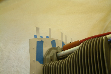
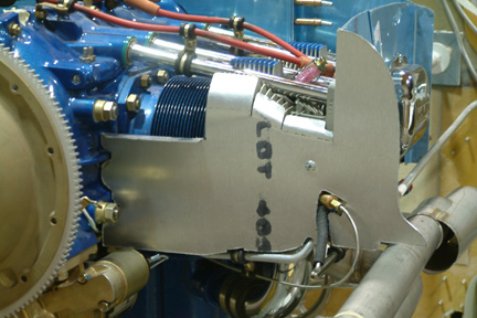
Trimming Van's Baffles
|
|
Then, I mounted the 'usable' Van's baffles (forward and sides) temporarily and taped the Plan's paper templates (w/paper strips) against them. I traced out the Plan's outline onto Van's template for trimming. As shown in the picture (left), there was quite a bit of trimming. The Van's baffles saved some time, but not a whole lot, in my opinion. However, it showed me how it should be fitted with the remaining baffles - a great learning process that earns good value points. Actually, I extended more height to the traced outlines such that the top of the baffles are about 1/4" from 'touching' the cowling - as suggested by the Plan.
[Hindsight] I revisited these baffles for final touch up and assembly, I realized that there were some nice stiffening attachments with the Van's kit. They made the side walls a lot more rigid than the Plan's baffles. |
Once the forward and side baffles (from Van's) were installed, I proceeded to the Plan's aft baffles. I made a set of paper templates by making copies of the Plans' baffle drawings onto thick 11"x17" papers (from Staples). Then I cut them out and started my trial fit process. Once all paper templates were fitted (with additional overlays and/or extra trimmings), I started with metal sheets per Plan.
|
|
|
Here's a picture of my aft left baffle. I deviated from Plan by dividing this baffle into two pieces because my left baffle will not line up with the right (due to the cylinder offset). In addition, the left baffle has to slide in ~1/2" such that I can bolt it flush against the alternator mount. Please do not hesitate to contact me if my description is not clear. |
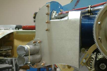
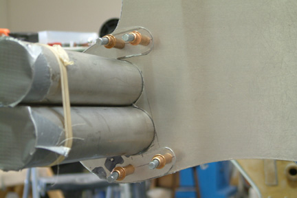
A closer look at a couple of seams (starter and exhaust pipes). It took a lot of trial and error to get there. I hope its worthwhile! |
Alternator Skirt
|
Top Inner Baffles
|
|
Then came the afterthought... What happens after engine shut down and the temperature rises? How much spacing do I need to accommodate the expansion? I decided to scrap the idea and post a question to the group... |
|
I bought some High Temp RTV (Copper +750F) from our local auto store, taped down the fin areas, wet out 2 layers of glass and laid it over the cylinder heads. I used duct tape because I wanted the baffles to be removable instead of a permanent install at this time. |
|
|
|
After it cured, I popped the entire assembly off and trimmed off the excess RTV/glass around the edges. I think it will work out OK. |
|
Here's a picture of the my inner baffles... |
Making it Shine!
Here's a couple pictures of my shinny baffles...the right aft view...and... |
 the
left aft view... the
left aft view...Eventually, I will either have it painted or anodized. However, I will wait after all the electrical hook ups are completed at a later date. |
Plugging the Hole
|
|
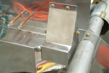
I eventually made a three piece cover as shown - one for the front and two side panels. They are held together with rivets. |
|
|
|
If you look close, you can see both lines.
[Hindsight] I decided to make the cowling fence and trim to width before I started trimming the baffles (explained below). |
Building the Fences
After trim, I re-bolted the cowling back on. With a marker, I re-marked the match line on the baffle surfaces. Adding 1/4" clearance from the fence trim line, I will have 3/4" clearance between the baffle to the inner cowling surface. It is important to note that the fences are slightly offset from the baffles as intended. |
|
|
Adding Neoprene Asbestos Strips
Instead of riveting the strips onto the baffles, somewhat permanently, I decided to make them removable. I made a matching strip (1/2" wide .032: thick aluminum) along the edges of the baffles. The strips are used to 'sandwich' the Neoprene strips in place. I drilled a set of 3/16" holes, 2" apart, 1/4" in from the baffle edges. I plan on using AN3 bolts and nuts through the baffles and the matching strips. |
 I
did not give it any thought regarding the differences between Van's cowling vs.
the Cozy cowling until the Van's baffles arrived. Substantial trimming will be
required. I taped the Cozy templates on my engine and mounted the top cowling back
on. Using small strips of paper and masking tape, I formed a rough profile of
the cowling along the Cozy paper templates.
I
did not give it any thought regarding the differences between Van's cowling vs.
the Cozy cowling until the Van's baffles arrived. Substantial trimming will be
required. I taped the Cozy templates on my engine and mounted the top cowling back
on. Using small strips of paper and masking tape, I formed a rough profile of
the cowling along the Cozy paper templates.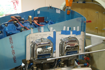
 Here's my left and right aft baffle with additional baffle
enclosing the exhaust pipes.
Here's my left and right aft baffle with additional baffle
enclosing the exhaust pipes.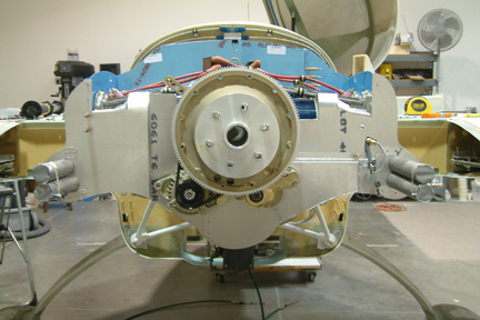
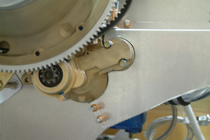
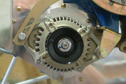 Due
to the swing of the alternator when tightening and loosening the belt, we have
to leave a big hole in the aft baffles to accommodate its movement. In order to
keep the hole covered up at all times, I had to make a 'skirt' that fits around the alternator.
My problem is that the face of the alternator is not parallel to the aft baffle.
therefore, the skirt has to cut across the body of the alternator, somewhat
diagonally. It was a real pain to get the skirt to fit nicely around the
alternator. I have made and discarded 4 different sets of skirts for one reason
or the other
Due
to the swing of the alternator when tightening and loosening the belt, we have
to leave a big hole in the aft baffles to accommodate its movement. In order to
keep the hole covered up at all times, I had to make a 'skirt' that fits around the alternator.
My problem is that the face of the alternator is not parallel to the aft baffle.
therefore, the skirt has to cut across the body of the alternator, somewhat
diagonally. It was a real pain to get the skirt to fit nicely around the
alternator. I have made and discarded 4 different sets of skirts for one reason
or the other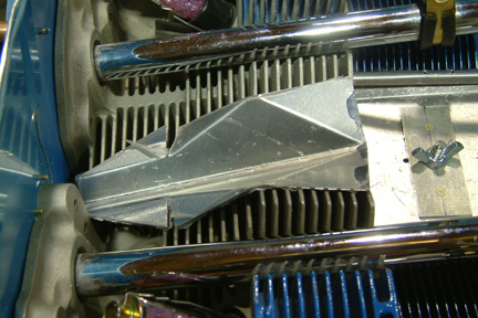 The inner top baffles are the
most challenging ones
The inner top baffles are the
most challenging ones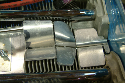 I
decided to make a two-halves baffle, rivet them together and tuck it in
the slot
(space) between the two cylinder heads (picture left).
I
decided to make a two-halves baffle, rivet them together and tuck it in
the slot
(space) between the two cylinder heads (picture left).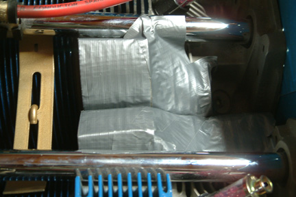 A couple of solutions were suggested by wetting
out a couple layer of glass with RTV and attach it directly onto the
fins...
A couple of solutions were suggested by wetting
out a couple layer of glass with RTV and attach it directly onto the
fins...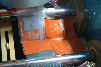 The RTV took a
couple of days to cure. To my disappointment, the RTV turned out to be a
soft rubbery cover instead of a rigid one - making it difficult to tie down
or secure.
The RTV took a
couple of days to cure. To my disappointment, the RTV turned out to be a
soft rubbery cover instead of a rigid one - making it difficult to tie down
or secure.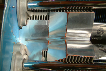 I decided to combine the two approaches. I divided the
baffles into 3 separate parts and made them out of thinner material (.020"
thickness). I also made a hold down arm out of a 1/4" aluminum tubing. Then I
re-taped the cylinder heads with packing tape and repeated the RTV method. This
time I pressed metal soft baffles over the RTV while it cures, making them as an
integral part.
I decided to combine the two approaches. I divided the
baffles into 3 separate parts and made them out of thinner material (.020"
thickness). I also made a hold down arm out of a 1/4" aluminum tubing. Then I
re-taped the cylinder heads with packing tape and repeated the RTV method. This
time I pressed metal soft baffles over the RTV while it cures, making them as an
integral part.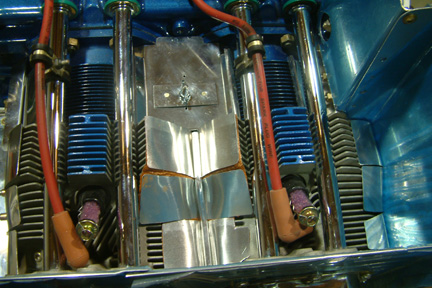
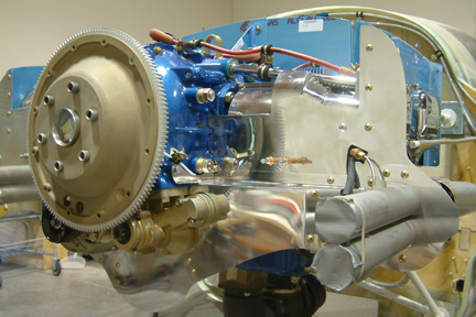 My
baffle set consists of a combination of Van's, Plans, my own design and the
inner bottom baffle that came with the engine. The fore and sides are Van's
baffles. The cylinder and aft baffles are per Plan. The inner baffles are
homemade. Once completed, I decided to buff them up and make them shine
My
baffle set consists of a combination of Van's, Plans, my own design and the
inner bottom baffle that came with the engine. The fore and sides are Van's
baffles. The cylinder and aft baffles are per Plan. The inner baffles are
homemade. Once completed, I decided to buff them up and make them shine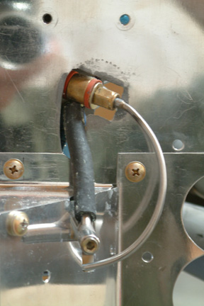 I
have an undesirable opening at the right rear baffle to give room to a
protruding fuel line. I tried using Play-Doh to form a mold for a glass cover -
without much success. Making it worse, the Play-Doh actually caused rusting
around the opening. I eventually had to remove the baffle and re-buff it to get
the rust marks off. I decided to make an additional cover for the entire mess.
The cover was somewhat difficult to make given the odd shape surroundings.
I
have an undesirable opening at the right rear baffle to give room to a
protruding fuel line. I tried using Play-Doh to form a mold for a glass cover -
without much success. Making it worse, the Play-Doh actually caused rusting
around the opening. I eventually had to remove the baffle and re-buff it to get
the rust marks off. I decided to make an additional cover for the entire mess.
The cover was somewhat difficult to make given the odd shape surroundings.
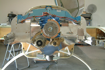 Here's
a look when all the sheet metal baffles are in place. Done...or so I thought.
How about the clearance between the baffles and the cowling, the cowling fences
and the rubbery baffles?
Here's
a look when all the sheet metal baffles are in place. Done...or so I thought.
How about the clearance between the baffles and the cowling, the cowling fences
and the rubbery baffles?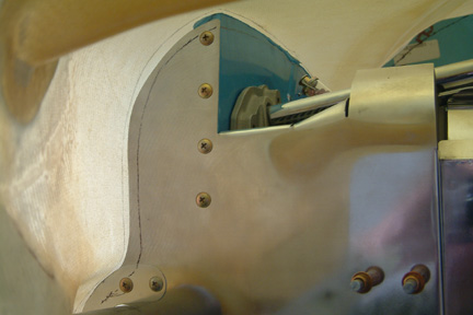 I
bolted the upper cowling back on to check the clearance between the inner
surface of the cowling and the edge of the baffles. It is important to maintain
certain clearance because the engine shakes a lot during start and shut
down. I trimmed a stir stick to 1/2" width and slid it against the gap between the
cowling and baffles. At the same time, I used a fine marker and traced out both
sides of the stir stick - one on the cowling and one on the baffle. The line on
the baffle is for trimming while the line on the cowling is the future cowling
fence line.
I
bolted the upper cowling back on to check the clearance between the inner
surface of the cowling and the edge of the baffles. It is important to maintain
certain clearance because the engine shakes a lot during start and shut
down. I trimmed a stir stick to 1/2" width and slid it against the gap between the
cowling and baffles. At the same time, I used a fine marker and traced out both
sides of the stir stick - one on the cowling and one on the baffle. The line on
the baffle is for trimming while the line on the cowling is the future cowling
fence line.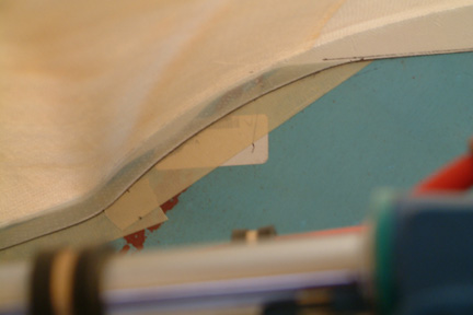 I
soon realized it is easier to build the fence by laying 2 BID on the cowling and
resting the angled surface against the baffles (cover with packing tape first).
Once cured, I popped the cowling off and laid 2 more layers against the back side
of the BID per Plan. After that, I marked and trimmed the fence to ~1/2" height.
Since the cowling was off the fuselage, trimming to consistent height was easy.
I
soon realized it is easier to build the fence by laying 2 BID on the cowling and
resting the angled surface against the baffles (cover with packing tape first).
Once cured, I popped the cowling off and laid 2 more layers against the back side
of the BID per Plan. After that, I marked and trimmed the fence to ~1/2" height.
Since the cowling was off the fuselage, trimming to consistent height was easy.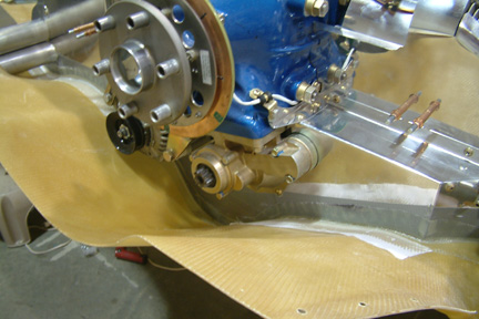 I
ended up adding a fence along both sides of the upper cowling (per Plan), the
forward side of the upper cowling (not to Plan), and the aft side of the lower
cowling (shown left, not per Plan).
I
ended up adding a fence along both sides of the upper cowling (per Plan), the
forward side of the upper cowling (not to Plan), and the aft side of the lower
cowling (shown left, not per Plan).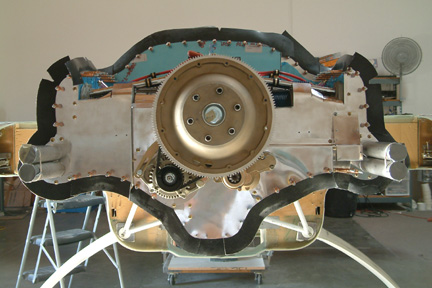 A
roll of black Neoprene Asbestos material was included in my Van's Baffle Kit, I
may as well use it. Surprisingly, I can cut it quite easily with a regular pair
of scissors.
A
roll of black Neoprene Asbestos material was included in my Van's Baffle Kit, I
may as well use it. Surprisingly, I can cut it quite easily with a regular pair
of scissors.