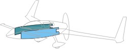
Chapter 5 - Fuselage Sides
| What's Up? |
 In
this chapter, we will be building the fuselage of the aircraft. The parts will
be BIG - since it take the full length of the plane except the nose and the
engine compartment. In addition, it will be curved. That should be interesting.
Quite a bit of wood working is required for this chapter - mainly for fixtures
and stuff. By the end of the chapter, we will be doing a large layup - expected
to take HOURS per the Cozy archives. In
this chapter, we will be building the fuselage of the aircraft. The parts will
be BIG - since it take the full length of the plane except the nose and the
engine compartment. In addition, it will be curved. That should be interesting.
Quite a bit of wood working is required for this chapter - mainly for fixtures
and stuff. By the end of the chapter, we will be doing a large layup - expected
to take HOURS per the Cozy archives. |
| Making the
Jigs (FJA to FJF) |
 The
first part of this chapter requires some wood working to prepare the jigs,
but it is pretty straight forward. The FJA (with curved edge) requires a bit
more attention than others. Since I wanted to make sure all 4 are exactly the
same, I tried to make the first one as precisely as I could. That means tracing
the curvature carefully, trimming close to the curvature with a band saw, then
…. sand, sand and sand to the contour line. After I accomplished that, I
trimmed and clamped
all four FJA’s together, then sand, sand and sand some more! Here’s a
picture how they turned out. The
first part of this chapter requires some wood working to prepare the jigs,
but it is pretty straight forward. The FJA (with curved edge) requires a bit
more attention than others. Since I wanted to make sure all 4 are exactly the
same, I tried to make the first one as precisely as I could. That means tracing
the curvature carefully, trimming close to the curvature with a band saw, then
…. sand, sand and sand to the contour line. After I accomplished that, I
trimmed and clamped
all four FJA’s together, then sand, sand and sand some more! Here’s a
picture how they turned out. |
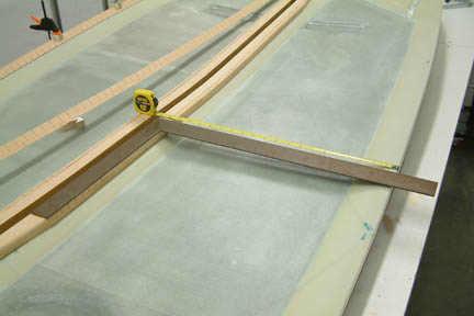
| Mounting the
Jigs on the Work Table |
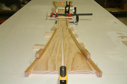 Once the jigs
were made, I bolted them down on the worktable. The plan requires a ½”
gap at the tip of the two ends – a perfect application for a laser beam.
I cut two 1”x½” wood blocks – one for each end of the jigs. I put a
mark at the mid-point of the ½” sides of the blocks. Now, I placed these small
blocks 102” apart (per plan) and ran the laser beam right down the center
of these two blocks. The laser beam is the center line of the jig set up as
shown. Once the jigs
were made, I bolted them down on the worktable. The plan requires a ½”
gap at the tip of the two ends – a perfect application for a laser beam.
I cut two 1”x½” wood blocks – one for each end of the jigs. I put a
mark at the mid-point of the ½” sides of the blocks. Now, I placed these small
blocks 102” apart (per plan) and ran the laser beam right down the center
of these two blocks. The laser beam is the center line of the jig set up as
shown.
Instead of using nails, I
pre-drilled the wood jigs and screwed them down onto the work table. This way, I
have less tendency to move them out of alignment while securing them in place.
Don't forget to double check the dimensions once they are secured. Now I am
ready to build the longerons.
|
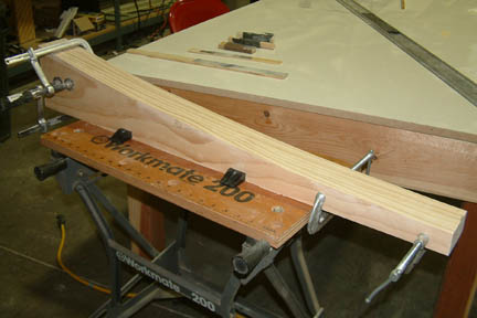
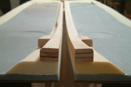
| Building the Longerons |
 The longerons were quite
straight forward. Between clamps, nails and wedge blocks, I managed to secure
the longerons in place to cure. I gave it 3 days to cure (while I built a local
heat tent). They popped off quite readily and retained their curvature - I was
impressed. The packing tape under the longerons did a great job in keeping the
longerons from sticking to the work table - thanks to the friendly advice from
the plans! The longerons were quite
straight forward. Between clamps, nails and wedge blocks, I managed to secure
the longerons in place to cure. I gave it 3 days to cure (while I built a local
heat tent). They popped off quite readily and retained their curvature - I was
impressed. The packing tape under the longerons did a great job in keeping the
longerons from sticking to the work table - thanks to the friendly advice from
the plans! |
Preparing the
Masonite Boards
First thing I noticed was that
there wasn't quite enough material for a 2-piece per side set up as shown in
the plans. Figure it is going to be another one of those 'creative' tight fit
layouts (as we all experienced in the past), I measured, re-measured and
re-measured some more... I finally gave up and ended up with 3-piece per side,
94"x21", 4"x21 and 4"x21". I was able to make both
masonite sides with a single 4'x8' board though. I later found out from the
archive, someone did mention briefly that there was not enough material for a
2-piece masonite per side - nothing specific though. Considered yourself
FOREWARNED!
| Making the Fuselage Sides |
 Foam for the fuselage sides
was
easy to cut with a razor blade. The curved edges at the bottom were not too bad
either. Again, I completed one side first, then I traced out the second side
using the first side as a template. This way, I should get two symmetrical sides
or at least a pretty close pair. Foam for the fuselage sides
was
easy to cut with a razor blade. The curved edges at the bottom were not too bad
either. Again, I completed one side first, then I traced out the second side
using the first side as a template. This way, I should get two symmetrical sides
or at least a pretty close pair. |
| Preparing Control Stick Clearance on
Fuselage Sides |
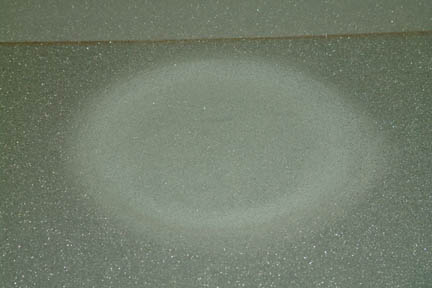 I
drew out the
positions of the control stick clearance (with a compass and felt tip) on both
of the fuselage sides and double checked its positions.
I used a plunge router with a flush router bit and milled out about 6"
diameter x .25" deep of foam. Used various grit sand-paper and shaped
a gradual slop that forms an 8" diameter clearance per
plan. I
drew out the
positions of the control stick clearance (with a compass and felt tip) on both
of the fuselage sides and double checked its positions.
I used a plunge router with a flush router bit and milled out about 6"
diameter x .25" deep of foam. Used various grit sand-paper and shaped
a gradual slop that forms an 8" diameter clearance per
plan. |
Preparing Fuel Gauge on Fuselage Sides
Next I carved out the fuel gauge indentation for the right side according to
plan - 19" from the rear edge... Marked out the pocket with a felt tip and start
gouging with various grits of sandpapers. Looked good! Now do the left side.
Fifteen minutes later ... done!
Stand back and admire my work of art and surprise.... they do not line
up????!!!! A quick measurement revealed that the right side was 12" from the end
instead of 19". How it got there ... I dunno. As warned by Mark Zeitlin -
measure, measure and measure - well, now I know what you mean!
One of the wonderful things about foam structures is that you can easily fix
your mistakes. I actually cut out the entire back panel (instead of filling up
the indentation) and re-carved the fuel gauge indentation at the correct
location. Scraping the back side of the panel makes Oops#2.
I later decided to use Vance Atkinson's LED fuel gauge indicator which requires
a flat .25" indentation instead of the slope surface. Arrrrg... but I convinced
myself that it will look pretty when its done!
Vance's fuel sight gauge arrived. It consists of a white plastic for the back
with a clear cover & a little pea size float. The white part is about 7.5" tall,
while the clear part is .25" wider all around. These dimensions are much larger
than the plan dimensions. The obvious question would be - where should I carve
the trough to accommodate these new fuel sight gauges?
 I posted the question to Vance
and was told to carve it with an extra .5" space all around such that I can
adjust its position after the strake is installed. Well, I ended up carving a trough the same size
as the white plastic (7.5"x2.5"), with a
.5" curvature starting 2.5" from the top edge of the fuselage, and
added another .5" curvature from the bottom of the trough back to the top
of the foam. I posted the question to Vance
and was told to carve it with an extra .5" space all around such that I can
adjust its position after the strake is installed. Well, I ended up carving a trough the same size
as the white plastic (7.5"x2.5"), with a
.5" curvature starting 2.5" from the top edge of the fuselage, and
added another .5" curvature from the bottom of the trough back to the top
of the foam.
Hopefully, the fuel sight gauge
will be at the right place when it is ready to install them. Incidentally, there's
wiggle room if I trim the fuel sight gauge to a smaller foot print as
well.
|
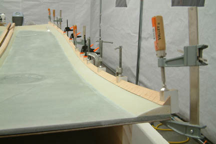
| Setting
Up the Fixtures for Fuselage Sides |
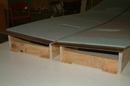 This
step requires the securing of the FJA - FJE fixtures at an upright position to
shape the fuselage sides prior to glassing. With the help of a laser beam, I
drew out the foot prints for the fixtures on the work table. Then I lined up the
fixtures on the foot print. I noticed some warpages on a few fixture boards
which I think needs to be corrected (I may be too picky on this one). I was
concerned that Bondo (as recommended per plan) may not be strong enough to hold and
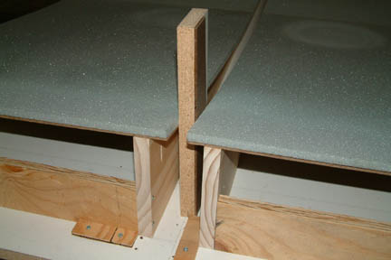
correct the warpages in my fixtures. I
decided to use Wayne Hick's approach by making fixture frames instead of gluing
them on the table instead. I cut up a bunch of 2.5"x 14.5"x.75"
plywood boards as spacers, screwed them to the fixture boards (5 places), forming a
fixture frame (as shown). This
step requires the securing of the FJA - FJE fixtures at an upright position to
shape the fuselage sides prior to glassing. With the help of a laser beam, I
drew out the foot prints for the fixtures on the work table. Then I lined up the
fixtures on the foot print. I noticed some warpages on a few fixture boards
which I think needs to be corrected (I may be too picky on this one). I was
concerned that Bondo (as recommended per plan) may not be strong enough to hold and
correct the warpages in my fixtures. I
decided to use Wayne Hick's approach by making fixture frames instead of gluing
them on the table instead. I cut up a bunch of 2.5"x 14.5"x.75"
plywood boards as spacers, screwed them to the fixture boards (5 places), forming a
fixture frame (as shown). |
  There
are two main advantages to this approach - 1) I can straighten out the warpages in
the fixture boards, and 2) I can hold the foam boards onto the masonite with
screws instead of 5 minute epoxy (per plan). This will eliminate the patch work
later when the foam fuselage is separated from the masonite boards. There
are two main advantages to this approach - 1) I can straighten out the warpages in
the fixture boards, and 2) I can hold the foam boards onto the masonite with
screws instead of 5 minute epoxy (per plan). This will eliminate the patch work
later when the foam fuselage is separated from the masonite boards.
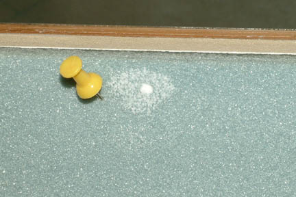
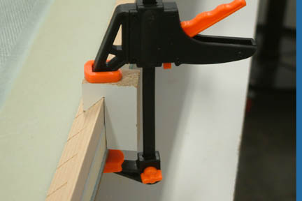
Fast
forward a bit here... the picture to the left shows the size of the hole
left on the foam by the hold down screws after the fuselage is done. They are
much smaller than the chunks of detached foam as described when using the
5-minute epoxy method. I filled them with micro before moving to Chapter 6. The
thumb tack is just for size reference.
|
 I made a 7/8" thick block
for lining
up the fuselage foam sheets as I 'pulled' them down onto the masonite (with screws
from the bottom side up). Surprisingly, the foam lays down on the masonite
boards quite nicely even without any screws to begin with. Nonetheless, when it was
done, they looked pretty good. I made a 7/8" thick block
for lining
up the fuselage foam sheets as I 'pulled' them down onto the masonite (with screws
from the bottom side up). Surprisingly, the foam lays down on the masonite
boards quite nicely even without any screws to begin with. Nonetheless, when it was
done, they looked pretty good. |
| Shaping
the Spacers |
|
I
followed the plans in forming the spacers. Two dimensions were missing from the
plans but I found them in the Archives:
 |
I
used the same slope dimension (identified in C-C) for the large spacer at
the aft end. |
|
I
started the heat duct slope 6" from the aft end of the fuselage and
extended the slope for 3.75". I followed Rick Maddy's footstep on this
one per his Web Site. |
 I
set up my band saw for rough cutting the slopes for the spacer strips. I then
sanded them to desired dimension with my HDSSS (Home Depot Sanding Stick
Special).
This foam is easy to shape, except it puts out lots of dust and they get
into Every Where! I added a couple inches to the spacer strips when I
shaped them because, I figure, when I attach them onto the curved fuselage sides,
it will add a bit of length to it - it did. I cut the spacers strips to
length before I was ready to micro them onto the
fuselage. I used a lot of C clamps to hold the spacers in place during
curing. I
set up my band saw for rough cutting the slopes for the spacer strips. I then
sanded them to desired dimension with my HDSSS (Home Depot Sanding Stick
Special).
This foam is easy to shape, except it puts out lots of dust and they get
into Every Where! I added a couple inches to the spacer strips when I
shaped them because, I figure, when I attach them onto the curved fuselage sides,
it will add a bit of length to it - it did. I cut the spacers strips to
length before I was ready to micro them onto the
fuselage. I used a lot of C clamps to hold the spacers in place during
curing. |
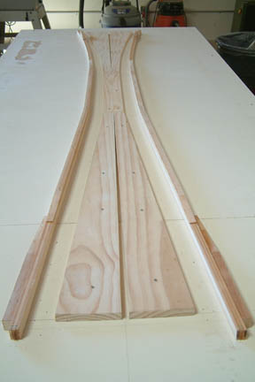
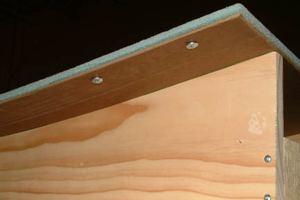
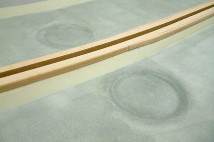
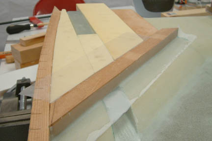
 Besides
rounding the foam spacers, I learned (from other builders) that the longeron
edges need to be rounded as well. Otherwise, the fiberglass will not lay down
nicely. I used a router to put a 1/4" rounded edge along the entire length
of the upper longerons. Initially, I was a bit concerned about the curved shaped
longerons and that the router may not sit right, however, it worked out OK. Here's a picture
of the longerons after I have the edges rounded. Besides
rounding the foam spacers, I learned (from other builders) that the longeron
edges need to be rounded as well. Otherwise, the fiberglass will not lay down
nicely. I used a router to put a 1/4" rounded edge along the entire length
of the upper longerons. Initially, I was a bit concerned about the curved shaped
longerons and that the router may not sit right, however, it worked out OK. Here's a picture
of the longerons after I have the edges rounded. |
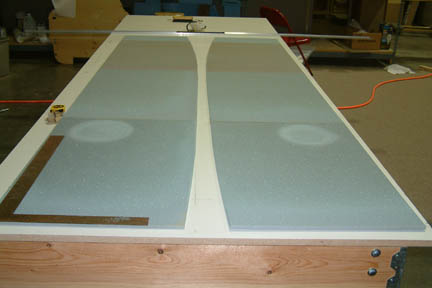
| Applying
UND onto Fuselage Sides |
|
This
step requires 2 layers of UND glass at 30 degrees over the entire inner
surfaces of the fuselage. If you have an opportunity to ask for a extra pair of
helping hands - this will be a good time to ask! I got Susann (my better half)
to help me lay out the UND on top of the fuselage so that I can pre-cut them
for subsequent layup. The pre-cut UNDs were rolled up, marked and placed under
cover to keep the dust out.
 I
microed both sides of the fuselage with Susann helping me
by mixing the micro. It took us 2.5 hours - much longer than expected!
I then proceeded to UND layup with Susann continuing on with epoxy supply. I took special care to push and pat down the glass at the stick
control and fuel sight curvatures. I was able to avoid the air bubble problems
many builders experienced. We did both sides at
the same time - without much of an air bubble problem - we were fortunate. I
microed both sides of the fuselage with Susann helping me
by mixing the micro. It took us 2.5 hours - much longer than expected!
I then proceeded to UND layup with Susann continuing on with epoxy supply. I took special care to push and pat down the glass at the stick
control and fuel sight curvatures. I was able to avoid the air bubble problems
many builders experienced. We did both sides at
the same time - without much of an air bubble problem - we were fortunate.
While the
layup was still wet, I trimmed the glass along the upper edges of the fuselages per plan with my electric scissors.
It was difficult to trim right up to the edges - I left about 1/16'' glass
overhanging. We were at hour 7 since the beginning of this task, I was getting tired and did not pursue perfection - I
should have.
|
Spacer
Board Preparation
Let
me digress a bit and discuss how I prepared the spacer boards. The plan calls for
7/8" spacer. Well, most lumber does not come in 7/8" thickness. As
you may recall, I have a neighbor that works for a lumber yard... A visit to the
neighbor (with cookies) and I got myself a 6'x 1' board, planed to 7/8"
thickness... the next day. I cut them into 8"x12" boards and wrapped them
with packing tape. The reason for the packing tape is to make sure they do not
stick to the flox that will ooze out between the longerons and the fuselage when
they are clamped together (refer to longeron installation in this Chapter).
Installing
the Longerons
After
I trimmed the glass along the top edges of the fuselage sides, I slipped five (5) 7/8"
spacer boards (prepared above) evenly between the fuselage
sides. I brushed flox onto the mating surfaces of the upper longerons and
upper edge of the fuselage and clamped them tight together. At this time, I was concerned about the 1/16" glass
(I left un-trimmed
earlier) because by pushing the spacer board down between the fuselage sides, I
was shoving the 1/16" glass (overhang) to fold down against the
foam of the fuselage sides. I used lots of
clamps to hold down the longerons onto the fuselage sides as well as to the
spacer boards. Strips of peel ply were added per plan. This layup took us a total of 9 hours
straight and we were exhausted when completed. My back was stiff for 3 days
afterwards.
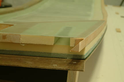
 After
a 24 hour cure, I couldn't wait to remove the clamps to
see the results. The folded
glass at the upper fuselage did not cause any problem because I squeezed them so
tight with clamps, they did not have any dimensional effect. The flox did not
stick to the 7/8" wood spacers either because of the packing tape. With
all the good news, I forgot to take pictures! The picture shows the aft spacers
- cured with 2 layers of UND. You can see the fuel
sight gauge and the electrical duct. The UND covering the electrical ducts needs to be trimmed
- later. The light in the background is my heat source
for my localized heat tent. I trimmed the glass overhang from the lower fuselage
edges at this time. After
a 24 hour cure, I couldn't wait to remove the clamps to
see the results. The folded
glass at the upper fuselage did not cause any problem because I squeezed them so
tight with clamps, they did not have any dimensional effect. The flox did not
stick to the 7/8" wood spacers either because of the packing tape. With
all the good news, I forgot to take pictures! The picture shows the aft spacers
- cured with 2 layers of UND. You can see the fuel
sight gauge and the electrical duct. The UND covering the electrical ducts needs to be trimmed
- later. The light in the background is my heat source
for my localized heat tent. I trimmed the glass overhang from the lower fuselage
edges at this time. |
Applying
the 4 layers of UND
The
instruction (for this task) is contained in a 44 word sentence - it took me 8
hours from preparation to completion!
First,
I un-rolled the UND on a long table making sure its straight and flat. I used
1" wide x 102" long strips of masking tape and taped along the full
length of the UND. I repeated this every 5" apart. Once taped, I used my
electric scissors and cut along the middle of masking tape - lengthwise. Since
the UND cloth is 30+" wide, I can make six 5" wide strips of UND, each
102" long. I made a total of 8 strips - 4 for each longeron. The tape keeps
the UND from fraying and allowed easy handling.
I
decided to epoxy the 4 UND layers together first before applying onto the
longerons. I cut a 6"x 105" 4 mil plastic strip and laid it down on a flat
surface. I placed the 1st UND layer on it and wet it with epoxy, followed by the
2nd, 3rd and 4th respectively - adding epoxy on each layer as necessary. Once
completed, I laid down another layer of 4 mil plastic on top (poor man's peel ply
method) and squeegeed out the excess epoxy. When all the bubbles were removed, I
used the electric scissors and trimmed off the rest of the masking tapes - leaving a
4+" x 102" strips of UND, sandwiched between 2 layers of 4 mil
plastic. I then transported the strips to the longerons, peeled off the top layer of
the plastic and laid it face down onto the longeron and spacer per plan. Don't
forget to brush a layer of fresh epoxy onto the longeron before applying the UND
though. Surprisingly, the UND laid down easier than expected. After removing the
remaining 4 mil plastic from the UND, I peel plied the UND to ensure a smooth
transition to the fuselage. After applying the peel ply, I re-laid the 4 mil
plastic back on top of the UND strips and squeegeed some more to ensure the UND laid
down nicely. I then covered it with the heat tent to help cure through the night.
| My
First Repair |
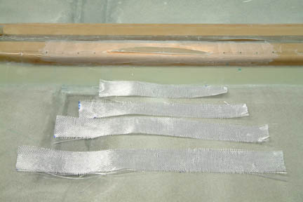 Well,
the bubble goblin made its first appearance overnight. I found a large bubble on the
longeron after cure. This will be my first repair. I re-read Chapter 3 repair instructions
and went for it. I ground out the 4 layers of glass where the bubble was. I then
stepped outwards 1 layer less every inch. Since it was a 4 layer UND, I stepped out 4
inches - both directions. You can see the size of the bubble and the 4 layers of replacement
UND -
ready to be glassed in. Once I got the 4 layers done, I added on more layers of
BID for the entire length (not shown). I then peel ply the entire repaired area.
The result looked ok ... I hope it is really OK! I'll show the repair to an
experienced builder next time when I get a hold of one. Well,
the bubble goblin made its first appearance overnight. I found a large bubble on the
longeron after cure. This will be my first repair. I re-read Chapter 3 repair instructions
and went for it. I ground out the 4 layers of glass where the bubble was. I then
stepped outwards 1 layer less every inch. Since it was a 4 layer UND, I stepped out 4
inches - both directions. You can see the size of the bubble and the 4 layers of replacement
UND -
ready to be glassed in. Once I got the 4 layers done, I added on more layers of
BID for the entire length (not shown). I then peel ply the entire repaired area.
The result looked ok ... I hope it is really OK! I'll show the repair to an
experienced builder next time when I get a hold of one. |
| Lower
Triangular Longerons |
 Accordingly
to the plans, I am suppose to check the
dimensions in Fig 5 and mark the exact
location of the lower longerons with a felt tip pen. With the white
spacers and upper longerons installed and no access from the bottom side of the masonite, there's no way I can measure and mark the locations EXACTLY
per fig. 5. I posted the question to the builder's group and got a few amusing
responses. Basically, the distance between the lower longerons from the upper
edge of the fuselage, should be close to the dimensions in Fig. 5. Most
importantly, the dimensions should be equal on both sides. I laid a carpenter's
square along the top edges of the longerons at designated locations per Fig. 5
and took measurements on opposite sides of the fuselage. Note that these
dimensions will not be the same as the ones in Fig. 5 because the dimensions are
no longer taken from a flat foam board as in the beginning. Here's the
dimensions I got and the variances between the two sides: Accordingly
to the plans, I am suppose to check the
dimensions in Fig 5 and mark the exact
location of the lower longerons with a felt tip pen. With the white
spacers and upper longerons installed and no access from the bottom side of the masonite, there's no way I can measure and mark the locations EXACTLY
per fig. 5. I posted the question to the builder's group and got a few amusing
responses. Basically, the distance between the lower longerons from the upper
edge of the fuselage, should be close to the dimensions in Fig. 5. Most
importantly, the dimensions should be equal on both sides. I laid a carpenter's
square along the top edges of the longerons at designated locations per Fig. 5
and took measurements on opposite sides of the fuselage. Note that these
dimensions will not be the same as the ones in Fig. 5 because the dimensions are
no longer taken from a flat foam board as in the beginning. Here's the
dimensions I got and the variances between the two sides: |
Front
|
20.10
|
20.55
|
20.85
|
21.00
|
20.95
|
20.82
|
20.80
|
20.50
|
19.90
|
19.00
|
17.61
|
Variance
|
0.00
|
-0.05
|
-0.05
|
+0.05
|
0.00
|
-0.08
|
+0.05
|
+0.05
|
+0.05
|
+0.05
|
0.00
|
Back
|
20.10
|
20.60
|
20.90
|
20.95
|
20.95
|
20.90
|
20.75
|
20.45
|
19.85
|
18.95
|
17.61
|
As
you can see, most of the variance is within .05" with a maximum at
0.08". I can probably sand down the high side and fill the low side when
installing the fuselage bottom. I decided to leave them as is for now and move
on to the next step.
 I anticipated that the lower longerons
would be a challenge due to the curvatures
it has to conform to. I did a lot of reading on the Web and learned a few useful
tricks. Instead of cutting relief cuts every 2 or 4 inches apart, I cut them
every inch and some on the alternative edges as necessary. I think that will put
less stress on the lower longerons during the curing process. You can see my
clamp-de-thrifty in the foreground. I found them on the Web - unbeatable price
of $1.71 a piece. I anticipated that the lower longerons
would be a challenge due to the curvatures
it has to conform to. I did a lot of reading on the Web and learned a few useful
tricks. Instead of cutting relief cuts every 2 or 4 inches apart, I cut them
every inch and some on the alternative edges as necessary. I think that will put
less stress on the lower longerons during the curing process. You can see my
clamp-de-thrifty in the foreground. I found them on the Web - unbeatable price
of $1.71 a piece. |
 For
curing, I cut up quite a few clamping blocks with 45 degree concave corners for
holding the triangular shaped longerons in place for curing. Susann reminded me to wrap
the face of the blocks with packing tape - what a life saver! The holding
clamps work very well and they popped off easily without sticking to the
epoxy. For
curing, I cut up quite a few clamping blocks with 45 degree concave corners for
holding the triangular shaped longerons in place for curing. Susann reminded me to wrap
the face of the blocks with packing tape - what a life saver! The holding
clamps work very well and they popped off easily without sticking to the
epoxy.
After
the 24 hour curing, I cut up the 20 inch long doublers as well as the relief
cuts to conform to the curvatures. Floxed in and clamped down, forming a square
cross section per plan. You can see the result in later pictures.
|
| Electrical
Channels |
 I
made the electrical channels using the male plug method as taught in the plans.
They turned out reasonably well without too much of a challenge. The only
difference I made (un-intentionally) was slanting the front tip to match the
edge of LWY. It butts well against LWY when installed, but it created a lot
more work for making the foam cover (fill) as directed in Fig.
17. I
made the electrical channels using the male plug method as taught in the plans.
They turned out reasonably well without too much of a challenge. The only
difference I made (un-intentionally) was slanting the front tip to match the
edge of LWY. It butts well against LWY when installed, but it created a lot
more work for making the foam cover (fill) as directed in Fig.
17. |
| LWX
& LWY |
 I
cut up the stringers per Fig. 12. For the 1" wide LWX, I used the base
dimension (15") and the two angles (45 & 35) respectively.
As for the 2" wide LWY, I used the two dimensions (8.6" &
6.5") respectively. When I tried to line them up per Fig. 14 & 16, they weren't even close. I pondered over this more than I should
have but come to the conclusion that the most important dimensions are the
aft cutouts (5.5" x 8.7" per Fig. 16) and the 16.3" position for
the LWX (Fig. 14). I
cut up the stringers per Fig. 12. For the 1" wide LWX, I used the base
dimension (15") and the two angles (45 & 35) respectively.
As for the 2" wide LWY, I used the two dimensions (8.6" &
6.5") respectively. When I tried to line them up per Fig. 14 & 16, they weren't even close. I pondered over this more than I should
have but come to the conclusion that the most important dimensions are the
aft cutouts (5.5" x 8.7" per Fig. 16) and the 16.3" position for
the LWX (Fig. 14).
If you
make LWX and LWY as I described above, the short edge of LWX will be 12.57" instead of
12.7" - just a bit short AND the angle for LWY will be
about 43.6 degrees. To make the whole thing fit nicely per plan, I trimmed LWY to
45 degrees and extended the length of the LWX (look close at the picture).
|
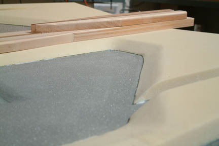
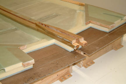
 After
floxing in the LWX and LWY in place, I filled in the area bounded by the lower
longerons, LWX and LWY with 3/4" Clark foam. I also embedded the
electrical channel in place per plan. Clamps were used to hold the Clark foam in
place during cure and were sanded leveled with the stringers. Filled the gaps
with micro and laid 6 plies of BID per direction. You can see the filled area,
trimmed glass and the embedded electrical channel (picture at left). After
floxing in the LWX and LWY in place, I filled in the area bounded by the lower
longerons, LWX and LWY with 3/4" Clark foam. I also embedded the
electrical channel in place per plan. Clamps were used to hold the Clark foam in
place during cure and were sanded leveled with the stringers. Filled the gaps
with micro and laid 6 plies of BID per direction. You can see the filled area,
trimmed glass and the embedded electrical channel (picture at left). |
| Trimming
the Fuselage Sides |
 I
made measurements to the fuselage sides using carpenter's square per plan. It
turned out that the length of both fuselages are
exactly 101.75" and square. I think I lucked out on this one. Only the vertical cuts on the
foam need to be trimmed. Since the trimming requirement was minimal, I
just sanded them down using the square as a guide. I did release the fuselage
from the masonite boards by removing the anchoring screws. The
size of the holes left on the foam by the anchoring screws were small and were
patched up easily (refer to earlier picture). I
made measurements to the fuselage sides using carpenter's square per plan. It
turned out that the length of both fuselages are
exactly 101.75" and square. I think I lucked out on this one. Only the vertical cuts on the
foam need to be trimmed. Since the trimming requirement was minimal, I
just sanded them down using the square as a guide. I did release the fuselage
from the masonite boards by removing the anchoring screws. The
size of the holes left on the foam by the anchoring screws were small and were
patched up easily (refer to earlier picture). |
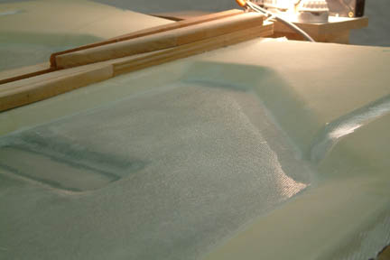
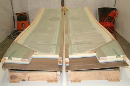 After
the sides were trimmed, I marked the 5.5" x 8.7" area
for the centerspar. I
cut the cured glass first with the FIEN tool along the marked outline. Once the glass were
cut, I took a jig saw
to the rest of the foam. I then sand down the glass and foam edges smoothly and
to exact dimensions. The two pictures to the right showed the cut out area as
well as the completed fuselage. After
the sides were trimmed, I marked the 5.5" x 8.7" area
for the centerspar. I
cut the cured glass first with the FIEN tool along the marked outline. Once the glass were
cut, I took a jig saw
to the rest of the foam. I then sand down the glass and foam edges smoothly and
to exact dimensions. The two pictures to the right showed the cut out area as
well as the completed fuselage. |
Part
Weight
Left
fuselage
10 LB 15.4 OZ
Right
fuselage
11 LB 0.6 OZ
1.2
Oz variance in weight between the two fuselage sides... maybe it will fly level!