 In this chapter, I will assemble the fuselage sides (from
Chapter 5) with all the bulkheads (from Chapter 4), build and
install the center keel and install the fuselage bottom. In other words, we are
going from 2D to 3D!
In this chapter, I will assemble the fuselage sides (from
Chapter 5) with all the bulkheads (from Chapter 4), build and
install the center keel and install the fuselage bottom. In other words, we are
going from 2D to 3D!| What's Up? |
| In this chapter, I will assemble the fuselage sides (from
Chapter 5) with all the bulkheads (from Chapter 4), build and
install the center keel and install the fuselage bottom. In other words, we are
going from 2D to 3D! |
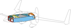
The plan called for trial fit of all bulk heads to each of the fuselage sides at the beginning of Chapter 6. However, I find it hard to do so without first marking their exact location on the inside of the fuselage sides - remember, the dimensions on the plan are parallel to the longitudinal axis and not along the curved longerons. In addition, I expect quite a bit of sanding on the bulkhead sides (where they meet the fuselage sides) for a good fit - sure hate to sand the wrong spot. I was especially concerned about the front seatback edges, since it rests along a ~45o angle to the fuselage sides. I decided to hold off on that a bit. Instead, I laid out the foot print of the fuselage assembly on the work table first, marked the bulkhead locations, then performed a preliminary trial fit, marked the contact locations, then did the sanding.
| Work Bench Setup |
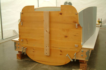 I chose to follow Wayne Hick's up-side
down assembly approach as many have done before me (Thanks Wayne). I replaced the regular legs
of my work bench with 8" legs that have adjustable feet for leveling. Then I
mounted the mock firewall against the back end of the work bench. I didn't realize
the extra height between the upper longerons and the top of the firewall, I had
to raise the work bench some more - to ~12" above ground. See the extra 4"x4"
blocks under the table legs and the clearance I got from the floor! I also screwed in a vertical
2x4 onto the table frame to provide a rigid support for the firewall.
Note the 2 holes in the firewall (where the upper
longerons will fit) are lined up to the surface of the work bench. Un-be-knownst
to me, I ended up taking this fuselage on and off many... many... many times before
getting serious in the assembly process! I chose to follow Wayne Hick's up-side
down assembly approach as many have done before me (Thanks Wayne). I replaced the regular legs
of my work bench with 8" legs that have adjustable feet for leveling. Then I
mounted the mock firewall against the back end of the work bench. I didn't realize
the extra height between the upper longerons and the top of the firewall, I had
to raise the work bench some more - to ~12" above ground. See the extra 4"x4"
blocks under the table legs and the clearance I got from the floor! I also screwed in a vertical
2x4 onto the table frame to provide a rigid support for the firewall.
Note the 2 holes in the firewall (where the upper
longerons will fit) are lined up to the surface of the work bench. Un-be-knownst
to me, I ended up taking this fuselage on and off many... many... many times before
getting serious in the assembly process! |
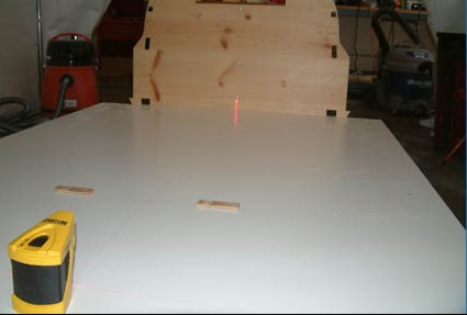 Since our fuselage is 101.75" long -
which is much longer than any T-square I can pick up from Home Depot, I chose to
use a laser for most of my alignments. As shown, I used a straight line laser to set a center line from the center of the firewall to the front of
the assembly (picture below left). I then used a cross-hair laser to mark the left and right
positions of all the bulkheads per plan. With a straight edge, I drew a
straight line joining the left & right marks on the work bench. I then
double checked
to make sure they were square to the centerline. All bulkhead positions are now
established and drawn on the work bench per plan. Since our fuselage is 101.75" long -
which is much longer than any T-square I can pick up from Home Depot, I chose to
use a laser for most of my alignments. As shown, I used a straight line laser to set a center line from the center of the firewall to the front of
the assembly (picture below left). I then used a cross-hair laser to mark the left and right
positions of all the bulkheads per plan. With a straight edge, I drew a
straight line joining the left & right marks on the work bench. I then
double checked
to make sure they were square to the centerline. All bulkhead positions are now
established and drawn on the work bench per plan. |
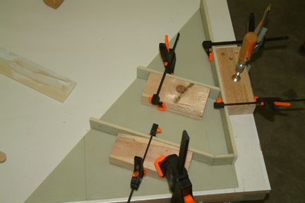
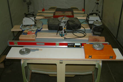
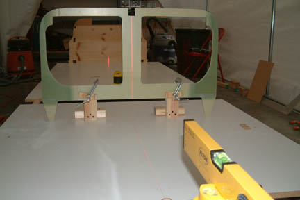 My next step was to secure some stops to
help in the bulkhead
placements. You can see the 2 wooden stops I screwed down for the front seat back
(60" from the front) per Wayne Hicks' recommendation. At the front end, I mounted 2 holding
blocks for positioning and securing the F22 at exactly 101.75" from the
face of the firewall. The vertical laser (at the foreground) helps to line up
the center of the F22 to the centerline of the fuselage. With the center line
established, the front (F22) and the back (firewall) secured, and the bulkhead
positions marked, the fuselage sides are ready to go on the work bench. My next step was to secure some stops to
help in the bulkhead
placements. You can see the 2 wooden stops I screwed down for the front seat back
(60" from the front) per Wayne Hicks' recommendation. At the front end, I mounted 2 holding
blocks for positioning and securing the F22 at exactly 101.75" from the
face of the firewall. The vertical laser (at the foreground) helps to line up
the center of the F22 to the centerline of the fuselage. With the center line
established, the front (F22) and the back (firewall) secured, and the bulkhead
positions marked, the fuselage sides are ready to go on the work bench. |
 Surprisingly, it took a lot of sanding
and wrestling to get the longeron ends and LWYs through the firewall holes. I was debating if I should trim the longerons OR change the hole
sizes in the firewall.
After reading the plan instruction several times, I think the instruction means
adjusting the hole sizes - I could be wrong here... but I did make sure the
inner edge
of the longeron ends (at the firewall) are equal distance from the center
line. Surprisingly, it took a lot of sanding
and wrestling to get the longeron ends and LWYs through the firewall holes. I was debating if I should trim the longerons OR change the hole
sizes in the firewall.
After reading the plan instruction several times, I think the instruction means
adjusting the hole sizes - I could be wrong here... but I did make sure the
inner edge
of the longeron ends (at the firewall) are equal distance from the center
line.
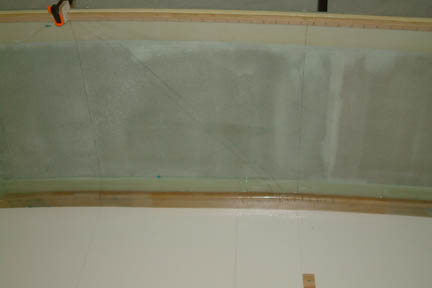
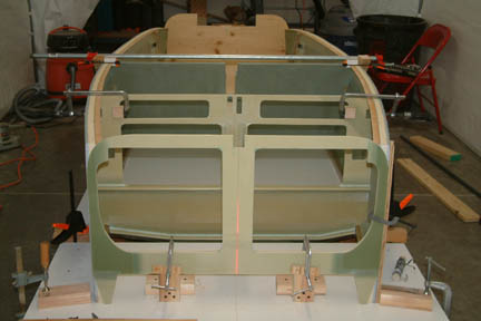
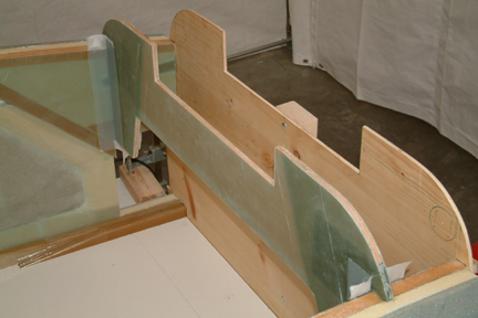
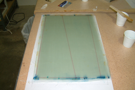
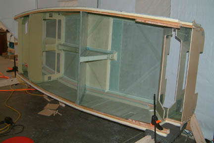
Once the longerons were in place, I extended the bulkhead positions (from the workbench surface) up the fuselage sides with the help of a self-leveling vertical laser line . You have to look real close to pick them out. I am confident with the bulkhead positions because I had established the front, back and centerline of the fuselage assembly footprint on the table earlier. I double checked their positions from the front and the back - because Nat used the word EXACTLY in the plans! You can also see the double 45 degree outline for the edges of the front seat. Now, I have a better idea where and how the edges need to be shaped for a good fit... |
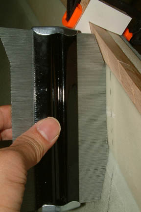 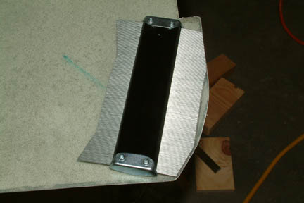 The profile, where the seat back meets
the lower longeron spacer was a tough one to determine. I got a carpenter's
profile widget from Home Depot (picture left) to help to transfer the profile onto the edge of
the seat back prior to trimming (picture right). It probably saved me many times in picking up,
trial fit, take down, sand some more... and just one-last-time... Regardless, I did many... many...
many... cycles of that until I was satisfied with the fit. The profile, where the seat back meets
the lower longeron spacer was a tough one to determine. I got a carpenter's
profile widget from Home Depot (picture left) to help to transfer the profile onto the edge of
the seat back prior to trimming (picture right). It probably saved me many times in picking up,
trial fit, take down, sand some more... and just one-last-time... Regardless, I did many... many...
many... cycles of that until I was satisfied with the fit. |
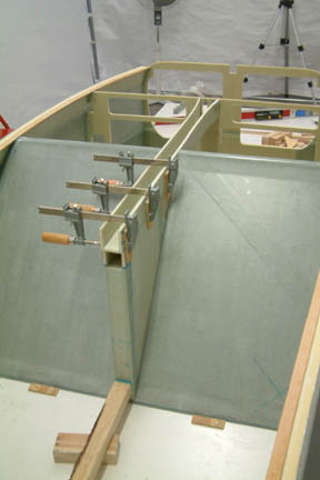
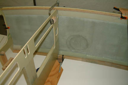 The second challenge was the positioning
of the Instrument
Panel since it will be sitting at the cut out of the table top. Since the front
position of the fuselage is known, I clamped a straight edge (board) at
19.25" for the IP (picture left) to push against. I then clamped a small
board, flush to the upper longerons, assuring the IP will rest flush with the
top (it will be the bottom here, since I
am working upside down) of the upper
longerons. The top clamp pulled the fuselage sides in, snug with the IP sides. I
made a couple of blocks with a slot just the thickness of the IP to make sure
the clamps won't slip during cure. The second challenge was the positioning
of the Instrument
Panel since it will be sitting at the cut out of the table top. Since the front
position of the fuselage is known, I clamped a straight edge (board) at
19.25" for the IP (picture left) to push against. I then clamped a small
board, flush to the upper longerons, assuring the IP will rest flush with the
top (it will be the bottom here, since I
am working upside down) of the upper
longerons. The top clamp pulled the fuselage sides in, snug with the IP sides. I
made a couple of blocks with a slot just the thickness of the IP to make sure
the clamps won't slip during cure.
The next step was to clamp everything down snug and tight, make sure everything is leveled both horizontally and vertically. Here's where the SmartTool becomes very handy. I also measured and marked the distances of the longeron edges to the center line at several critical locations to make sure the fuselage sides are symmetrical and lined up. You can see some of the "push" blocks along the outside edges of the fuselage - just for that purpose. |
 Generally, my SmartTool showed
0.0o, 0.1o and 0.0o along the top of front seatback,
IP
and F22 respectively. It also measured 89.7o and 89.8o
vertically along the face of F22 and IP
respectively, and 47.7o
on the front seat back. I did a calculation on the slant of the seatback
according to the plan dimensions with consideration to the thickness of the
material, it turned out to be 47.63o. I'll say that's close
enough. I then pre-drilled and put 4 screws through the F22
onto
the upper and lower longerons. Generally, my SmartTool showed
0.0o, 0.1o and 0.0o along the top of front seatback,
IP
and F22 respectively. It also measured 89.7o and 89.8o
vertically along the face of F22 and IP
respectively, and 47.7o
on the front seat back. I did a calculation on the slant of the seatback
according to the plan dimensions with consideration to the thickness of the
material, it turned out to be 47.63o. I'll say that's close
enough. I then pre-drilled and put 4 screws through the F22
onto
the upper and lower longerons. |
At this time, trial fit is complete! I
re-checked all dimensions one more time and was ready for the next step -
floxing!!! ![]() Rats, I ran out of hardener...
Rats, I ran out of hardener... ![]() to be continued.
to be continued.
The floxing effort was not too bad. The left fuselage moved a tiny bit forward but I did not realize it until I was done. It was late and I did not push for perfection...again. I sweated over the night (after I got home) thinking about it and hope that I do not have to cut out the bulkheads and re-do the assembly. Rush to work the next morning and performed the following measurements:
| Actual | Should | |
|
Fuselage level (across the top) |
0.1o |
0.0o |
|
Fuselage left front vertical |
89.7o |
90.0o |
|
Fuselage right front vertical |
89.6o |
90.0o |
|
Front seatback horizontal |
0.0o |
0.0o |
|
Front seatback slant |
47.6o |
47.6o |
|
Instrument Panel horizontal |
0.1o |
0.0o |
|
Instrument Panel vertical |
89.7o |
90.0o |
|
F22 horizontal |
0.1o |
0.0o |
|
F22 vertical |
89.6o |
90.0o |
I noticed some settling occurred during cure but not much. Though I did not hit the angles dead on in most occasions, but the variances are relatively small. I don't think I would be able to see the difference if I had used a square.
| Glass All Corners |
 The next step is to glass side corners with 2 plies of BID. This effort took a bit longer than expected. I followed the
plan instructions and had no major problems. The only thing I did not like was
that my flox fillets (around the corners) were not perfectly rounded. To correct
that - I wrapped a piece of 80 grit sand paper around a 1/4" diameter wood
dowel and gave them all a nice sanding. There's got to be a better way to do
this! The next step is to glass side corners with 2 plies of BID. This effort took a bit longer than expected. I followed the
plan instructions and had no major problems. The only thing I did not like was
that my flox fillets (around the corners) were not perfectly rounded. To correct
that - I wrapped a piece of 80 grit sand paper around a 1/4" diameter wood
dowel and gave them all a nice sanding. There's got to be a better way to do
this!
I used the BID tape method for all corners. However, I made the length of the BID just a tad short of the vertical lengths. It is because the BID tape method leaves sharp edges around the tape (since they are cut to dimension after multiple layers) and I like to leave a nice tapered edge all around. The extra space allows me to form the tapered edges by the use of peel ply as called for by the plans. All in all, I did not have much problem with this operation. |
| Glass the F22 Hard Points |
 The 4 ply enforcement turned out to be
quite simple. Again, I used the BID tape method and tapered the edges with peel
ply. I did have to come back to trim and smooth out the edges after cure. The 4 ply enforcement turned out to be
quite simple. Again, I used the BID tape method and tapered the edges with peel
ply. I did have to come back to trim and smooth out the edges after cure.
|
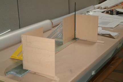
Installation of F28 took a bit more thought and alignment. First, I had to open up the width of the gap on work bench to accommodate F28 since it protrudes above the upper longerons. Now the gap is ~12" wide - enough to handle both the Instrument Panel and F28. Following general consensus, I moved F28 from 5.9" (per plan) to 6.25" from the forward face of F22. Since F28 is hanging over the gap, it was difficult to set and square up the 6.25" position on the upper longerons. I did the following:
 I
first projected a straight line from the forward face of F22 down onto the
workbench. If you look closely, you can see the fine F22 projection line
intersecting the center line. Using a square against the 'cross-hair', I found
the 6.25" position over the gap. Using 2 large clamps, I clamped a straight
piece of 2x4, with its aft face at 6.25" and parallel to the F22 projection
line. Then I slipped the F28 against the aft face of the 2x4 and clamped against it with
3 small clamps. They kept the F28 at 6.25" position as well as vertical. I
added 2 more clamps at both ends of F28 and double checked their distance from
the F22 projection line. I also confirmed the center line of F28 lining up with
the fuselage center line and verified the vertical face with a bubble. I
first projected a straight line from the forward face of F22 down onto the
workbench. If you look closely, you can see the fine F22 projection line
intersecting the center line. Using a square against the 'cross-hair', I found
the 6.25" position over the gap. Using 2 large clamps, I clamped a straight
piece of 2x4, with its aft face at 6.25" and parallel to the F22 projection
line. Then I slipped the F28 against the aft face of the 2x4 and clamped against it with
3 small clamps. They kept the F28 at 6.25" position as well as vertical. I
added 2 more clamps at both ends of F28 and double checked their distance from
the F22 projection line. I also confirmed the center line of F28 lining up with
the fuselage center line and verified the vertical face with a bubble.
I then disassembled all the clamps, floxed the mating surfaces, re-clamped and re-verified. After cure, I added the 2 layer BID and peel ply. |
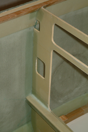
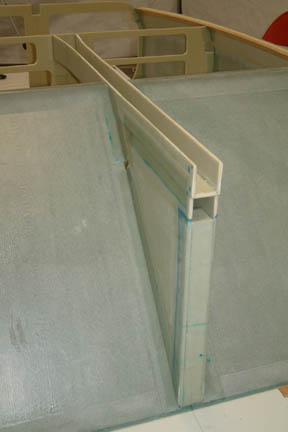
| Aft Bulkhead Installation |
 My
aft bulkhead was a bit wider than the width of the fuselage especially at the
ears. I had
to sand the edges (bulkhead) down to fit. I just used a sanding block to remove
the excess while keeping a close eye on the center line - to make sure I am not
taking too much from one side of the bulkhead than the other. Picture shows a
fitted and glassed aft bulkhead. I glassed both the forward and aft corners
using BID tape method. I measured their orientation after cure and it registered
90o vertical...perfect! My
aft bulkhead was a bit wider than the width of the fuselage especially at the
ears. I had
to sand the edges (bulkhead) down to fit. I just used a sanding block to remove
the excess while keeping a close eye on the center line - to make sure I am not
taking too much from one side of the bulkhead than the other. Picture shows a
fitted and glassed aft bulkhead. I glassed both the forward and aft corners
using BID tape method. I measured their orientation after cure and it registered
90o vertical...perfect! |
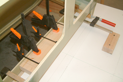
| Forward Bulkhead (Lower) Installation |
 I
built the 8" box fixtures and hot
glued them onto the lower forward bulkhead per plan. You can see the 90o
squares I used to prop up the box fixtures to make sure they stay perfectly
vertical. A 12"x1/4" drill bit was used to check out the fit at the corners. I
built the 8" box fixtures and hot
glued them onto the lower forward bulkhead per plan. You can see the 90o
squares I used to prop up the box fixtures to make sure they stay perfectly
vertical. A 12"x1/4" drill bit was used to check out the fit at the corners.
|
 Just
as the aft bulkheads, the upper forward bulkhead has to be sanded down a bit to
fit. I also did a bit of sanding on the 'side ears' at the lower longerons to
make sure the bulkhead is perfectly horizontal as well. I had to use many
clamps to keep the bulkhead level and square for floxing. After cure, I taped all
4 corners with the 2" BID tapes - though I did not see specific
instructions in the plans. I think it is a prudent thing to do. Just hope it
won't bite me later. After cure, the next day, I drilled the holes with the 12"x1/4" drill bit. I then removed the fixture box as directed. Just
as the aft bulkheads, the upper forward bulkhead has to be sanded down a bit to
fit. I also did a bit of sanding on the 'side ears' at the lower longerons to
make sure the bulkhead is perfectly horizontal as well. I had to use many
clamps to keep the bulkhead level and square for floxing. After cure, I taped all
4 corners with the 2" BID tapes - though I did not see specific
instructions in the plans. I think it is a prudent thing to do. Just hope it
won't bite me later. After cure, the next day, I drilled the holes with the 12"x1/4" drill bit. I then removed the fixture box as directed.
|
| Forward Bulkhead (Upper) Installation |
 My
upper forward bulkhead was about 1/8" wider on both sides - a bit more than
sanding can do to fit. I trimmed both edges with the table saw instead. The
fortunate part is that the edges turned out to be nice and straight - they fit
snuggly against the fuselage walls. Once I floxed the mating surfaces and fit
it, it stayed up in place on its own. But I know better than leaving it alone
through the night for cure. I clamped a couple of 2x4s under LWX for support. I also
taped up the middle sections to make sure the part stayed put during cure. My
upper forward bulkhead was about 1/8" wider on both sides - a bit more than
sanding can do to fit. I trimmed both edges with the table saw instead. The
fortunate part is that the edges turned out to be nice and straight - they fit
snuggly against the fuselage walls. Once I floxed the mating surfaces and fit
it, it stayed up in place on its own. But I know better than leaving it alone
through the night for cure. I clamped a couple of 2x4s under LWX for support. I also
taped up the middle sections to make sure the part stayed put during cure.
|
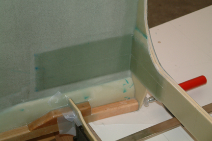
 After
cure, I prepared the 2" BID Tapes and the 6 layer UND for the aft corners
and face respectively. Since the 'ears' of the bulkhead are symmetrical and if I
flip them head-to-toe, they form a perfect rectangle (as shown). To make life a
bit simpler, I cut out 6 layers of rectangular shaped UND and made a 6 layer UND
tape. Then I drew out the required shape & dimension on the sandwiched UND (by 4-mil plastic). I trimmed along the lines with my electric scissors and viola...
my UND tapes are ready for glassing. After
cure, I prepared the 2" BID Tapes and the 6 layer UND for the aft corners
and face respectively. Since the 'ears' of the bulkhead are symmetrical and if I
flip them head-to-toe, they form a perfect rectangle (as shown). To make life a
bit simpler, I cut out 6 layers of rectangular shaped UND and made a 6 layer UND
tape. Then I drew out the required shape & dimension on the sandwiched UND (by 4-mil plastic). I trimmed along the lines with my electric scissors and viola...
my UND tapes are ready for glassing.
I glassed the BID tape corners first, then the UND tapes and then peel ply. The one thing you must be careful is the orientation of the UND per plan. The diagonal cut edges need to be laid against the fuselage sides for the correct UND orientation. I caught it in the last minute and had to make minor trimming to compensate. Otherwise, this method worked well for me. |
I laid out the seat brace per drawing shown in Chapter 2, page 5 to maximize the use of foam, but I misunderstood the instruction in Chapter 6, page 4, second paragraph - I glassed one side of the seat brace BEFORE cutting them apart. By the time assembly comes along, one side of the seat braces has the glass on the wrong side. Fortunately, both sides of the seat brace will be glassed anyway, I went ahead and glassed the other side prior to assembly.
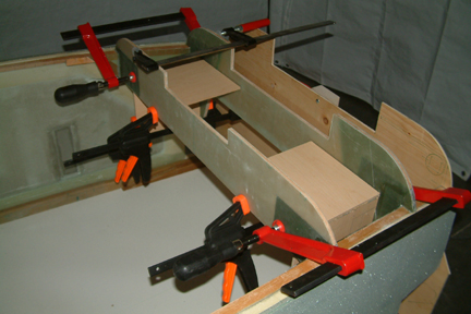
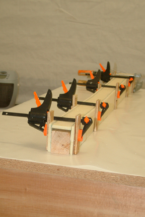
  I floxed
in the inside spacers using blocks and clamps instead of nail method as
suggested per plan. I am just not comfortable with putting nails through the
glass and foam for positioning parts for cure. I think nails in foam allows room
for the part to shift during cure compared to clamps. That's just
me. As shown, the blocks are there to make sure the spacers stayed vertical
to cure - I am not sure nails will do the same. To attach the second half
of the seat brace, I added a longer 2x4 along the hypotenuse edge of the
triangle (shown right). The top just 'drops' in place for a good fit - no nails.
I laid a couple 5 pound weights on top for added pressure. You can also see a
couple of wood block spacers along the edges to make sure there is no sagging on the
edges. I floxed
in the inside spacers using blocks and clamps instead of nail method as
suggested per plan. I am just not comfortable with putting nails through the
glass and foam for positioning parts for cure. I think nails in foam allows room
for the part to shift during cure compared to clamps. That's just
me. As shown, the blocks are there to make sure the spacers stayed vertical
to cure - I am not sure nails will do the same. To attach the second half
of the seat brace, I added a longer 2x4 along the hypotenuse edge of the
triangle (shown right). The top just 'drops' in place for a good fit - no nails.
I laid a couple 5 pound weights on top for added pressure. You can also see a
couple of wood block spacers along the edges to make sure there is no sagging on the
edges.
The 2 BID layers on the sides of the seat brace went smoothly. However, I did not round off the edges along the back and the sides when I did the back layers. I knew that could be a problem, but figured I can force the glass to conform. Well, they have better will than I do - I ended up fighting it for 2.5 hours and gave up. I ended up removing the 2 BID layers and peel ply, waited overnight for the epoxy to dry out, then rounded off the edges. The 2 BID layers and peel ply went on nicely in 30 minutes. Lesson learned - no cheating! |
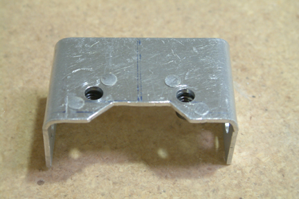 Forming
the aluminum fuel valve bracket was not too bad. I cut out the flat pattern with
my band saw and bent the 2 sides (90o) carefully without causing a
crack in the bend. I used a vise and wood block with appropriate radius. I also drilled the required holes with my drill press. I was
not able to find my countersink bit for the rivets, therefore, I used a 3/8" drill
bit instead. It turned out OK. Forming
the aluminum fuel valve bracket was not too bad. I cut out the flat pattern with
my band saw and bent the 2 sides (90o) carefully without causing a
crack in the bend. I used a vise and wood block with appropriate radius. I also drilled the required holes with my drill press. I was
not able to find my countersink bit for the rivets, therefore, I used a 3/8" drill
bit instead. It turned out OK. |
| Heat Duct |
 I laid
out the heat duct the same as the seat brace and ended up with glass on the wrong side for
one of the sides. Just as the seat brace, I glassed the other side and proceeded
to the assembly step. I should have known, when both sides of the foam are glassed,
it is stiff as a board and it is not going to bend for the front opening.
I ended up using the FEIN tool to 'fillet' the glass off
the foam. Surprisingly, it went ok! I had to do a little bit of patching on the
surface foam - but nobody will ever know when it is covered with 2 layers of glass later. It
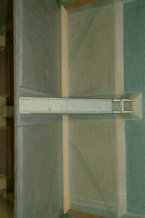
also saved me a trip to Aircraft Spruce to buy extra foam. I
cut up a straight 1.5" x 40" wood core to shape the heat duct (left). I kept
the wood core a bit short (in height) such that it won't make any contact with
the seam above or flox. It would be a real fun job (if not impossible) to
separate them if they got floxed together. After cure, I sanded a groove on
the foam for the 2" seat belt anchor and the opening for the fuel lines per
plan. I laid
out the heat duct the same as the seat brace and ended up with glass on the wrong side for
one of the sides. Just as the seat brace, I glassed the other side and proceeded
to the assembly step. I should have known, when both sides of the foam are glassed,
it is stiff as a board and it is not going to bend for the front opening.
I ended up using the FEIN tool to 'fillet' the glass off
the foam. Surprisingly, it went ok! I had to do a little bit of patching on the
surface foam - but nobody will ever know when it is covered with 2 layers of glass later. It
also saved me a trip to Aircraft Spruce to buy extra foam. I
cut up a straight 1.5" x 40" wood core to shape the heat duct (left). I kept
the wood core a bit short (in height) such that it won't make any contact with
the seam above or flox. It would be a real fun job (if not impossible) to
separate them if they got floxed together. After cure, I sanded a groove on
the foam for the 2" seat belt anchor and the opening for the fuel lines per
plan. |
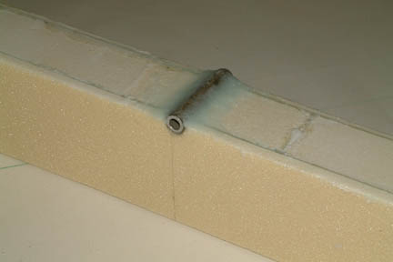  When
installing the 7 layers glass over the 2" seat belt tube, I had a lot of
difficulty to get the glass to lay down nicely over the tube - even
with a
single layer. I can just see a 'king size' delamination will erupt right above
the tube. I eventually removed all the glass layers and re-floxed the 2" tube
with a heavier than normal build up at the fillet. The resultant lay up turned out much
smoother. Picture (right) includes the 2 BID layers as well. When
installing the 7 layers glass over the 2" seat belt tube, I had a lot of
difficulty to get the glass to lay down nicely over the tube - even
with a
single layer. I can just see a 'king size' delamination will erupt right above
the tube. I eventually removed all the glass layers and re-floxed the 2" tube
with a heavier than normal build up at the fillet. The resultant lay up turned out much
smoother. Picture (right) includes the 2 BID layers as well. |
| Attaching Heat Duct |
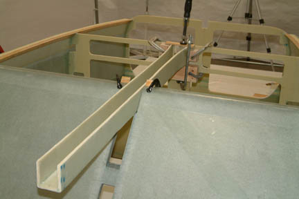 Instead
of attaching the seat brace to the heat duct per plan, I decided to flox the
heat duct to the instrument panel / seat back first. It is because I will have
more flexibility to maneuver the heat duct for perfect alignment and perform
minor shaping of the seat brace to the slope of the seat back if required. I used multiple
blocks and clamps to hold the heat duct (both front and middle) to perfectly
level (0.0 degrees) position for curing. You may not be able to see my
alignment laser beam that is dead on the alignment mark at the end of the heat duct
(recall my alignment laser beam runs along the middle of the fuselage, connecting the mid point of F22 to the
mid point of the firewall). Instead
of attaching the seat brace to the heat duct per plan, I decided to flox the
heat duct to the instrument panel / seat back first. It is because I will have
more flexibility to maneuver the heat duct for perfect alignment and perform
minor shaping of the seat brace to the slope of the seat back if required. I used multiple
blocks and clamps to hold the heat duct (both front and middle) to perfectly
level (0.0 degrees) position for curing. You may not be able to see my
alignment laser beam that is dead on the alignment mark at the end of the heat duct
(recall my alignment laser beam runs along the middle of the fuselage, connecting the mid point of F22 to the
mid point of the firewall). |
| Attaching the Seat Brace |
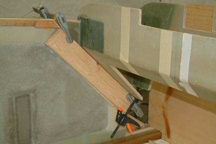
 After the heat duct
was cured, I trial fit the set brace. As expected, I have to make a bit of
trimming to the diagonal edge for good fit. Basically, I have to change the
slope of the seat brace to match the slop of the seat back. With the band saw, I
took ~1/8" of materials (max) to eliminate all gaps. I used three clamps to
hold the seat brace in place (do not forget to apply packing tape on the surface
of clamping blocks). In addition, I used a 1"x1" pole to prop
up the seat brace at the bottom (as shown). Once the seat brace is aligned and
held up tight in place, I floxed it in. After the flox is cured, I applied the 2
layer BID tapes along the sides and to the heat duct. After the heat duct
was cured, I trial fit the set brace. As expected, I have to make a bit of
trimming to the diagonal edge for good fit. Basically, I have to change the
slope of the seat brace to match the slop of the seat back. With the band saw, I
took ~1/8" of materials (max) to eliminate all gaps. I used three clamps to
hold the seat brace in place (do not forget to apply packing tape on the surface
of clamping blocks). In addition, I used a 1"x1" pole to prop
up the seat brace at the bottom (as shown). Once the seat brace is aligned and
held up tight in place, I floxed it in. After the flox is cured, I applied the 2
layer BID tapes along the sides and to the heat duct. |
| Completed Seat Brace & Heat Duct |
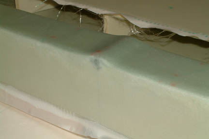
 Generally,
the heat duct and seat brace assembly was not too difficult. The 2 mistakes I
made were not rounding off the back edges of the seat brace before glassing and
not having a heavy enough buildup of flox at the 2" seat belt tube. They both
required me to re-do the operation. However, they were valuable lessons which I
used in subsequent steps. The resultant heat duct is lined up along the center of
the fuselage (center laser) and leveled (0.0o). The seat brace is
measured at 90.0o vertical. Generally,
the heat duct and seat brace assembly was not too difficult. The 2 mistakes I
made were not rounding off the back edges of the seat brace before glassing and
not having a heavy enough buildup of flox at the 2" seat belt tube. They both
required me to re-do the operation. However, they were valuable lessons which I
used in subsequent steps. The resultant heat duct is lined up along the center of
the fuselage (center laser) and leveled (0.0o). The seat brace is
measured at 90.0o vertical.
On to the fuselage bottom .... |
| Additional Spacers |
| Fuselage Bottom Frame |
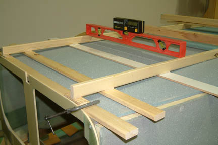 I
thought the fuselage bottom frame was going to be tough to build, but it turned out
simpler than expected. I started with the two 1x2 stringers. I cut them to
length - from aft face of F22 and forward face of the forward landing gear
bulkhead. Then I laid them on the flat spots on the fuselage bottom with the
overhangs at both ends. I
thought the fuselage bottom frame was going to be tough to build, but it turned out
simpler than expected. I started with the two 1x2 stringers. I cut them to
length - from aft face of F22 and forward face of the forward landing gear
bulkhead. Then I laid them on the flat spots on the fuselage bottom with the
overhangs at both ends.
Then I placed the two end cross beams (against F22 & FLGB), making sure they are leveled and clamped tight. Then I added a bit of weight (such as a couple 2x4s) across the stringers at the flat spots. The 2x4s keep the strings from moving as I add shims at the overhangs. I found the wooden stir sticks with some sanding make excellent shims for this application. I put a digital level across the stringers as I added the shims. Once leveled, I tacked them all down with a glue gun. |
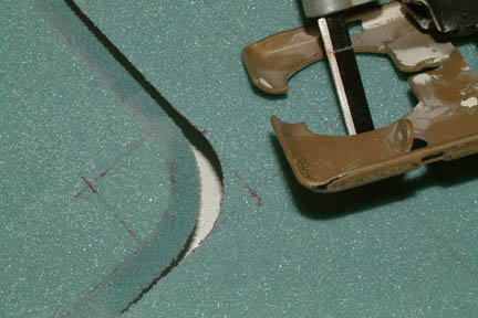
| Speed Brake |
|
With a bit of pondering, I finally made the leap of faith. I first drew the outline of the speed brake on the foam and with the 1" rounded corners using my round corner template. I then marked the quadrant lines and center of the rounded corners (as shown). If you look closer, I also placed a red mark on the jig saw alignment plate. It happens that the distance between the mark and blade is exactly 1". I also found a smooth jig saw blade - perfect for smooth cut on foam materials.
I first precut the jig saw entry point with a regular razor blade. Then I slipped the jig saw blade in and started with the beveled straight edge. As I approached the round corner cuts (pre-marked by the quadrant lines), I started the turn by following the cut line along the radius and at the same time making sure my mark on the jig saw alignment stays right on top of the center of the radius. The result is a nice rounded beveled corner for the speed brake. Since the blade is thin and has no teeth, hardly any foam gets removed - just like a razor cut. When I placed the door back in place, you could hardly see the seam. |
| Fuselage Bottom |
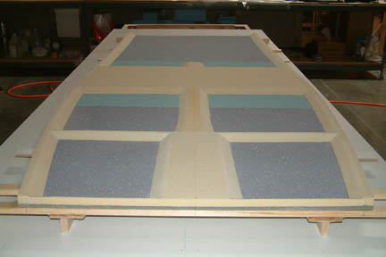 The
spacers for the fuselage bottom were not too difficult because we have gone
through a similar process when building the fuselage sides. I set up the band saw
and trimmed the spacer strips to 30o as needed. Don't forget to round
off the top edges of the spacers before glassing! The
spacers for the fuselage bottom were not too difficult because we have gone
through a similar process when building the fuselage sides. I set up the band saw
and trimmed the spacer strips to 30o as needed. Don't forget to round
off the top edges of the spacers before glassing!
I did not glass the fuselage bottom, flox and tape it to the fuselage in one operation per plan. I glassed and peel plied the fuselage bottom first and waited for it to cure overnight. I wondered if I should have floxed and taped it to the fuselage all at once - that would save me time on the peel ply. Nonetheless, I had the opportunity to inspect the glass work and filled a few small air bubbles that crept up along the spacer edges while I wasn't looking! |
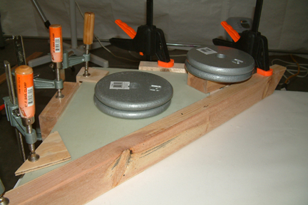
 I double checked the
leveling of the fuselage before floxing the fuselage bottom on. I checked the
leveling again after everything was weighted down for cure. As you can see, I put
a lot of weights on to weigh the edges down. Can you see the kitchen sink? (Got
you looking... I double checked the
leveling of the fuselage before floxing the fuselage bottom on. I checked the
leveling again after everything was weighted down for cure. As you can see, I put
a lot of weights on to weigh the edges down. Can you see the kitchen sink? (Got
you looking... |
| BID Tape All Edges |
 Instead
of putting the BID tapes on edges with the fuselage up side down, I turned the
fuselage side ways. That made the task much easier and I got better
quality results. Up to this point, I never felt I had a good grasp of the whole
floxing process. The surface of the flox was always rough and I always had a
tough time with air bubbles. UNTIL I caught one of John Slade's write
ups where he suggested smoothing it out by brushing epoxy over it with a brush.
I applied this technique throughout the BID tape operation. I first applied
medium dry flox along the edges and smoothed them out (the best I could) with a
mixing stick. Since the flox is somewhat dry, the surface will not be very
smooth (as expected). Then I followed up with a brush with just a bit of epoxy. The flox
absorbed the epoxy and smoothed out nicely - almost like magic!
I then laid down the BID tapes and peel plied over it. I turned out the best flox
radius since the start of the project. Instead
of putting the BID tapes on edges with the fuselage up side down, I turned the
fuselage side ways. That made the task much easier and I got better
quality results. Up to this point, I never felt I had a good grasp of the whole
floxing process. The surface of the flox was always rough and I always had a
tough time with air bubbles. UNTIL I caught one of John Slade's write
ups where he suggested smoothing it out by brushing epoxy over it with a brush.
I applied this technique throughout the BID tape operation. I first applied
medium dry flox along the edges and smoothed them out (the best I could) with a
mixing stick. Since the flox is somewhat dry, the surface will not be very
smooth (as expected). Then I followed up with a brush with just a bit of epoxy. The flox
absorbed the epoxy and smoothed out nicely - almost like magic!
I then laid down the BID tapes and peel plied over it. I turned out the best flox
radius since the start of the project. |
| BID Tape Seatback (rear edge) |
 The
instructions did not say much about what to do with the rear edge of the front
seatback. It has an acute angle (~47o) and its almost impossible to
get to as far as BID tape is concerned. I searched through the archives and someone
did post the question a while back. The only response was from Nat; to flox some
foam to it. Here's what I did: The
instructions did not say much about what to do with the rear edge of the front
seatback. It has an acute angle (~47o) and its almost impossible to
get to as far as BID tape is concerned. I searched through the archives and someone
did post the question a while back. The only response was from Nat; to flox some
foam to it. Here's what I did:
I set up my band saw and cut out two strips of foam about 20" x 1.5" x 1.5" (that makes a 45o angle). I shaped the ends to fit into the outside corners where the seat meets the fuselage sides and bottom. Its a bit of a complex angle, but foam is not too hard to shape - you just need patience. Then I floxed them in and BID tape them all in one operation. The foam spacer made the job a bit easier, but you still need triple jointed elbows and 10 inch long fingers to reach those far away places to keep the bubbles out. The end result was better than expected, but I ended up with a headache for the rest of the night... |
and that's the end of
Chapter 6 ![]()
![]()
![]() !!!
!!!
 Due to the excellent
glide characteristics of the Cozy, a speed brake was designed to slow it down in
flight. The speed brake consists of a 14"x22" door located at the
fuselage bottom which can be deployed electronically. Construction of the speed
brake requires a 45o beveled cutout at all sides with 1" radius
rounded corners - carved out of the fuselage bottom foam. I dreaded this cut for
days because I didn't have a good grasp of how to achieve a perfect cut. The
beveled cuts along the straight edges would probably be OK, but the transition from
straight edge to rounded corner concerned me a bit.
Due to the excellent
glide characteristics of the Cozy, a speed brake was designed to slow it down in
flight. The speed brake consists of a 14"x22" door located at the
fuselage bottom which can be deployed electronically. Construction of the speed
brake requires a 45o beveled cutout at all sides with 1" radius
rounded corners - carved out of the fuselage bottom foam. I dreaded this cut for
days because I didn't have a good grasp of how to achieve a perfect cut. The
beveled cuts along the straight edges would probably be OK, but the transition from
straight edge to rounded corner concerned me a bit.